
Research and Development of Power System Dispatching Microcomputer Billing System
Aiming at the current situation that the research and development of power grid dispatching system is basically blank, this paper proposes a new method suitable for the research and development of power grid dispatching microcomputer billing system. The method is based on the design idea of ​​network graph theory and coordinate positioning, and realizes the functional requirements of software system through object-oriented programming language. The paper will introduce the theoretical basis of software system and the function of software system and programming of object-oriented language. achieve. At present, the system has been put into operation in the East China Network, and the operation is in good condition, which reflects the effectiveness and scalability of the method.
Key words: power grid dispatching automation; command ticket; object-oriented method; graph theory; coordinate positioning method
The Researching and Developing of Dispatching Order
Sheet GeneraTIng System in Electric Power Load Dispatching System
LIU Wen-ju1, QIAN Luo-jiang1, LIU Wen-xian2
(1.Electric Engineering School of Wu Han University Electric & Engineering School, 430071, China)
2. Da Tong Power Supply Co., Shan Xi Province, 037008, China)
Abstract: This paper presents a novel method that suits the Researching and Designing of Dispatching Order Sheet GeneraTIng System in Electric Power Load Dispatching System.. The theoreTIcal basis of the method is Graph theory and Coordinate orientaTIon, which is explained in detail in this paper. In addition, the realization of software system and programming are introduced. The practical application of the software system proved that this method is effective.
Key words: Power Load Dispatching; OOP (Object Oriented Programming); Dispatching order sheet; Graph theory; Coordinate Orientation
0 Introduction At present, the software research and development of microcomputer invoicing is mostly carried out around the switch operation ticket. The software research and development for the power grid dispatching command ticket is basically blank.
The power grid dispatching order ticket microcomputer billing system performs more functions than the switch operating ticket system, and the system is more complicated to implement. In the past, the microcomputer billing system for the switch operation ticket was mainly defined by the developer's definition of the grid system structure and operation rules while developing the software. Compared with the actual staff, it is inevitably limited and unprofessional, and even less practical. The running experience summarizes the new operational rules. The grid scheduling complexity and flexibility requirements cannot be met. Therefore, in the grid dispatching system of the power grid dispatching order ticket, the development idea of ​​the microcomputer billing system can not be used again, and a new solution must be proposed.
This paper introduces a method based on graph theory and coordinate positioning, as well as the functional realization of software system and the programming implementation of object-oriented language. The system not only has the advantages of the previous graphical operation interface of the microcomputer billing system, but also has the advantages of vivid and intuitive operation, convenient operation and quick operation, and more prominently, the versatility and flexibility of the actual system users are realized. The efficiency and the pass rate of the microcomputer billing system of the power grid dispatching order ticket are greatly improved.
1 The theoretical basis of the software system The scheduling operation is to cut or put in electrical equipment. From the perspective of graph theory, the scheduling operation changes the topology of the graph. On the basis of abstracting components into points, the electrical properties are summarized into positional properties and stateal properties. At this time, the graph becomes a collection of points and their property relationships. The graph divides the traditional matrix into two when stored in a computer: one for recording network component devices and the other for recording component operating states. When performing the coordinate positioning search operation of the figure, first determine the position of the operated component in the whole figure, and then find the record of the component according to the position to the stored data structure of the figure, and proceed to the next step. The above is the basic idea of ​​the coordinate positioning method.
The specific implementation method of coordinate positioning method in software development is as follows: the graphical interface takes the upper left corner as the origin, and the right and downward directions are the positive direction, and the whole view is divided into 50×50 small areas, each area is used. To display a graphic of a device object. Thus, the attributes of each device graphic on the interface have x and y coordinates. According to the coordinate values ​​in the device properties, the position of the corresponding graphic on the view can be determined.
1.1 Realization of Mathematical Model of Grid Topology According to the theory of graph theory, the entire grid topology can be described as: ![]()
Where: Gi(i=1, 2..., N) is a substation in the power grid, and S, P are a set of position and state attributes of all components in each substation.
1.2 Storage of Graphs in Computers G is a substation. The network topology is divided into grids. Each grid has at most one point representing the component. The position matrix is: 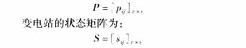
Where: when there are components at the grid (i, j); Pij, sij have records; when there are no components at the grid (i, j), Pij, sij are empty.
1.3 Coordinate positioning method of the graph For a substation G(S, P), there is one station internal component w. When establishing the network topology map, first define the position of the component in the position matrix: ![]()
When operating on a component, first find the element p(w) that matches the location property of the component in the P matrix, and then shift the state property of the component to the operational requirements.
The operation of the component must first meet the limits of the rule settings. In the topology data structure of the system, the state of the operated component and the related components are to be consistent with the state restrictions of these components in the rule. Implement these rules with logical relationships. To operate on component w, first find the state of the component in the state matrix based on the position matrix:
s(w)=[sij]v×v ![]() w
w
Then use the same method to find the state of other components related to it, and then judge according to the logic of the scheduling rule. When the logical relationship is established, the operation can be performed, that is, the state in the matrix is ​​replaced with a new state; if the logical relationship is not established, then Cannot operate.
2 Functional analysis of the software system
2.1 Characteristics of power grid dispatching command tickets (1) Power grid dispatching Each dispatching command may involve more than one substation, and the switching operation is only for a specific substation.
(2) There are many operational components involved in power grid scheduling. The switching operation mainly involves three kinds of two-state components: switch, knife gate and ground knife.
(3) In the power grid dispatching, the component status is no longer defined as the switching operation according to the two states, but is defined by four states: maintenance, cold standby, hot standby, and operation.
(4) The definition of each component state of the line and the substation in the grid dispatching is usually related to itself and a number of related components, and multiple logical relationships must be considered.
(5) The power grid dispatching procedure is more complicated than the switching operation procedure. It must not only consider the regulations formulated by the relevant state departments, but also comprehensively consider the actual situation of each region according to the principle of safety and efficiency.
Based on the above analysis, the grid dispatching order ticket microcomputer billing system should have the following functions.
2.2 Functional requirements of the software system
2.2.1 Editable function with grid structure The structure of the grid (such as wiring diagrams, etc.) can be constructed by the user. Moreover, when the grid structure changes (such as increasing or decreasing substations or equipment), users can edit and modify the grid structure and power station structure.
2.2.2 User-editable function with operational logic rule base Users can not only set logic rules according to the actual grid structure, but also require users to increase or decrease and define new logic rules according to the actual grid structure. The reason why the user can be edited is because the user's understanding of the rules and the mastery of the operating experience of the unit is unmatched by anyone else. Only the user itself has the ability to formulate a sequence of operations that is consistent with both the uniform security principle and the local special circumstances. At the same time, only the user itself has the ability to determine whether a command ticket is correct or not, and is responsible for the eligibility of the order ticket. .
2.2.3 Automatic detection and judgment function with logic rules According to the grid structure and the logic rules set by the user, each operation can be automatically checked, judged and realized.
2.2.4 With vivid and intuitive operation simulation platform and simulation operation function, the billing work should be carried out on the vivid and intuitive graphical interface. The related manipulated component graphics can be automatically displaced with the billing process, which translates the operator's billing method into The simulation operation preview is implemented, and each operation step is verified by the rules. If the rules are formulated correctly, the qualification of the opened operation ticket can be fully guaranteed.
2.2.5 Functions with hierarchical management of operation tickets Operation tickets must be managed hierarchically. Managers and operators must have different operation and editing rights.
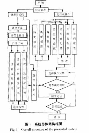
The above points are the main functional requirements of the system. Figure 1 shows the overall functional block diagram of the system.
3 software system programming design points The system uses Visual C++ as the development platform, using the characteristics of object-oriented language, can avoid the information redundancy in the description, and enhance the use and management of knowledge, easy to maintain.
3.1 Description of the software system object
3.1.1 Grid Objects The scheduling operation divides the operation of the equipment into four states: “overhaulâ€, “cold standbyâ€, “hot standby†and “runningâ€. According to the different number of equipment states in the scheduling operation term, the primary equipment can be divided into the following categories: four-state components: switches, capacitors, low-voltage reactors (overhaul, cold standby, hot standby, operation); three-state components: high-voltage reactance (Maintenance, cold standby, operation); two-state components: knife gate (divided, combined), transformer, busbar, outlet (overhaul, cold standby); non-operating components: generator, substation internal connection line.
3.1.2 Scheduling Command Ticket Objects Each dispatch command ticket has not only a series of operation statements, but also related to the state before and after the substation operation. Therefore, when establishing a dispatching command ticket object, it is also necessary to consider the state of the grid operation before and after billing.
3.2 Determination of the class and its object properties
3.2.1 Electrical component classes and their derived classes Using the characteristics of OOP, the inheritance relationship is determined for each device class, and the parent class, the basic component class, is abstracted according to the common properties of each electrical device, and different electrical component subclasses are derived. Encapsulate other device classes (such as lines and text classes) that cannot be operated to prevent misoperation.
The basic component class has the common characteristics of all component classes. Each derived component class inherits these common features and has its own unique properties to form a collection of electrical component classes.
3.2.2 Determination of object properties Start with the most basic component object class. The basic component class is the parent class of all component classes. The properties it should have are the component name, the component number, the component attribute (used to dispatch the custom name in the command ticket), and the coordinate position of the component corresponding graphic on the interface.
For derived classes, there are other properties. The properties of the four-state component are: four state definitions, current state and past state, four-state operation rules; three-state component attributes: three state definitions, current state And past state, three-state operation rules; the properties of two-state components are: definition of two states, current state and past state, two-state operation rules.
The properties of the substation are: the name of the substation, the current state of the station (whether the station is active from the perspective of computer operation), the status of the equipment in the station, the status of the secondary protection equipment in the station, and the chain data collection of various components. The power grid is composed of substations, and the main data is the chain data set of substation class objects.
At the same time, in the system development, the scheduling command, the scheduling task and the grid running state change records before and after the operation are all regarded as the attributes of the scheduling command ticket object, that is, the data.
3.3 Programming Implementation of Class Objects and Methods
3.3.1 Implementation of class objects The programming language describes each basic component class and derived class, and the derived class automatically inherits the properties of the basic component class. For example, the implementation of the basic component class: 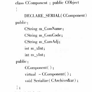
3.3.2 Implementation of a class method A method is a code unit defined in a class that describes the algorithm for the operation of the data structure and the operation of the object.
The various methods of design can be divided into the following categories: constructing object methods, including general constructors and destructors; setting and getting functions for basic properties; class name identification functions; deleting object methods; others (for specific functions) And the method of setting).
For example: a function of the knife type, its function is to detect the state of the knife according to the definition of the knife. 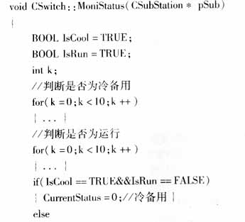
3.4 Graphical interface function design
3.4.1 Display of graphics From the object-oriented point of view, a single electrical device is used as a basic class object, and the primary wiring diagram of the substation displayed on the computer screen is a combination of the corresponding graphics of these individual electrical devices.
First, for each device object class, create a bitmap resource to indicate the undefined state when the device is not put into operation, and then design the corresponding bitmap resource according to the state of the device. When drawing a substation wiring diagram, fill in the component code, component number and component at the corresponding coordinates in a grid marked with vertical and horizontal coordinates according to the site conditions. The system uses the coordinate positioning method according to the coordinates and the component code to display the component and the component number at the corresponding position.
3.4.2 Displacement of component graphics during operation The scheduling operation in the power system is a series of operations to change the operating state of the electrical equipment for a certain task. The graphical interface of the billing system has a click operation function. To change a component from A state to B state, click the left mouse button on the component graphic, the system determines the coordinate value of the small region to which the click position belongs, and finds the data record of the component object according to the coordinate value to obtain the component. The name, number, current state and other attribute values. Then, a dialog box pops up to display the component attribute value, and the operator can change the component status in this dialog box. After the determination, the status value of the component object inside the system is also The corresponding change.
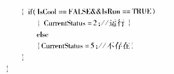
3.4.3 The setting rules of the operation rules are stored in the component class object in a certain data form. When operating, first search for related components to see if their status meets the requirements of the rule, and then judge whether the operation can be performed safely. The way to limit the state of certain components is expressed. There may be several restrictions on each of the operational rules, as long as any one of them is met. So change the setting of the operation rule to the limit of the state of the relevant component, and set each rule to one row. The rule setting input interface is shown in Table 1. Each row represents a constraint, and each three columns represents the state of a specified component.
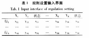
Each line of setting conditions will perform the following logical operations: 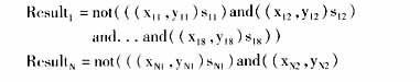
![]()
The last logical result can be made by performing an OR operation between rows and rows:
RESULT=(Result1)or(Result2) ...or(ResultN)
If the result is true, then the operation can be performed and the result is false, then the operation is not executable.
4 Conclusion This power grid dispatching microcomputer billing system has been put into operation in East China Network. From the operation situation, the system has stable performance, flexible and simple operation, fast ticket issuing speed and good versatility. It can not only guarantee the current operation mode, but also can adapt to the grid system structure change and add substation to complete the dispatching command ticket. Generate and manage. The system has a high application promotion value in the generation and management of dispatching command tickets.
Water Block is a heat-absorbing device of water cooling system. The water block is attached to the chip closely. Absorbing the heat emitted by the chip at any time to achieve the effect of heat transfer.Water block also has CPU Water Block and Gpu Water Block these two types, respectively bear the heat transfer function of the two.The water block is made of red copper, because the thermal conductivity of copper is better than other metals, and the price is moderate, which is the ideal material for water block.There are tiny channels inside the water block, and the water flow takes away heat quickly and ensures the normal work of the chip.
Water Block
Water Block,Acrylic Copper Water Block,Liquid Cooling Water Block,Copper Cpu Water Block
Dongyuan Syscooling Technology Co., Ltd. , http://www.syscooling.com