
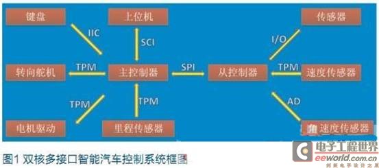
The basic construction of the system is shown in Figure 1, including sensor signal acquisition and processing, power motor drive, steering servo control, and control algorithm software development.
This article refers to the address: http://
Introduction of dual core
At the beginning of the design of the smart car, we analyzed that in the smart sensor design system based on photoelectric sensor, the signal integrity is important, that is, the more the track information and the position information of the car are obtained by the sensor, the better. By comparing the number of interfaces and performance requirements of 8-bit and 16-bit microcontrollers, the design decided to use two 8-bit microcontrollers MC9S08DZ60 as the core control unit.
Basic system construction
Dual core communication interface SPI
During the running of the vehicle, the information of the three sensors needs to be collected by the controller, which are photoelectric sensor, speed sensor and angular velocity sensor. Since the angular velocity sensor needs to have an accurate sampling period, we use the internal timer of the microcontroller to generate a 1.2ms time reference. The data acquisition of the three sensors is performed in this 1.2 ms cycle, and the SPI data transmission procedure is executed when the timer overflow is interrupted. SPI is a high-speed, full-duplex, synchronous communication bus that occupies only four lines on the pins of the chip, namely mosi, miso, sck, ss. We use a 1MHz data transfer speed, using 3 bytes to send sensor data, and two bytes to send speed sensor and angular velocity sensor data.
Communication interface between control system and host computer SCI
The running condition of the vehicle during driving is not directly observable, so we use the host computer system for real-time monitoring. Use wap200b wireless serial port module to send data, the module uses 3.0V power supply, built-in high-speed MCU, high data transmission accuracy. The communication between the MCU and the module uses a standard serial port, which is set to 115200 baud rate, 8 data bits, 1 stop bit, and no parity. A total of 7 data is sent in one communication. First, send two data as handshake signals are 0x00 and 0xFF respectively, then use 3 bytes of data to send sensor information, 1 byte of data to send angle information, 1 byte of data to send speed information, and the last bit to be reserved. Extended use later, send 0x00.
Communication interface between keyboard and main control chip I2C
When the vehicle is actually commissioned, there are many parameters that need to be continuously debugged, such as the corner and speed of the PID parameter vehicle. It will take time and effort to re-download the program each time when setting different parameters, so here we use the keyboard to enter the parameters when the vehicle is driving. The keyboard control chip HD7279 is a smart display driver chip with a serial interface that can simultaneously drive an 8-bit common cathode digital tube (or 64 independent LEDs). The chip can also be connected to a keyboard matrix of up to 64 keys. The chip can complete all functions of LED display and keyboard interface.
We use the four I/O ports of the microcontroller to operate the HD7279, which are CS, CLK, DATA, and KEY. Here we can set some parameters through the keyboard, such as the Kp, Ki, Kd parameters of the PID, the speed of the line and the curve.
Application of A/D module in collecting angular velocity
The A/D conversion module in this system is mainly used to collect the output value of the gyroscope. Since the analog gyro cost is relatively low, and the angular accuracy requirement is not very high in the vehicle model control system, the simulated gyro is used to correct the vehicle body posture in real time. The MC9S08DZ60 integrates a 12-bit analog-to-analog conversion channel. Since the analog gyro output signal range is 0~5V, the reference voltage of the single-chip microcomputer is +5V, which is separately powered by the high-precision voltage regulator module to ensure the accuracy of the conversion. The data processing procedure after A/D conversion is as follows:
Void Gyro_Process(void)
{
If(Gyro_Start == 1)
{
Unsigned int Max,Min,i,Value;
Signed long Sum;
Gyro_Data_Num = 0;
While(Gyro_Data_Num < 13)
{
Gyro_Collection();//AD conversion data acquisition function
}
Gyro_Start = 0;
For(i=1,Max=0,Min=0xffff,Sum
=0;i<13;i++)
{
Value=Gyro_Data_BUF[i];
Sum+=Value;
If(Max
Max=Value;
If(Min>Value)
Min=Value;
}
Sum= Sum-Max-Min ;
SUM_Test = Sum;
CarAngel_V=((((signed long)(Sum/10)- (signed long)Gyro_MidValue)*10000)>>16);
/Limiting processing /
If(CarAngel_V > 0)
{
CarAngel_V = (CarAngel_V *
1013) / 1000;
}
If(CarAngel_V<0)
{
CarAngel_V = (CarAngel_V *
1004) / 1000;
}
If(CarAngel_V>32767)
{
CarAngel_V=32767;
}
If(CarAngel_V<-32767)
{
CarAngel_V=-32767;
}
If(Gyro_Calibration_Flag == 1)
CarAngelRate = (unsigned int)
(CarAngel_V + 32767);
Else
CarAngelRate = 32767;
}
}
Application of TPM module in servo motor
The MC9S08DZ60 has eight independent PWM channels, which can independently configure the PWM frequency and duty cycle. The highest frequency is the bus clock frequency of 20MHz, which can meet the control of the servo and motor. At the same time, this module also has two counter modules, which can collect the motor speed value returned by the code disc for use in speed closed loop control. The PWM initialization in the motor control is as follows:
Void Motor_init(void)
{
TPM2SC = 0x00; /* Stop and
Reset counter */
TPM2MOD = VV_MAX; / / 15khz / * Period value setting * /
(void)(TPM2C0SC == 0); /* Channel 0 int. flag clearing (first part) */
/* TPM2C0SC: CH0F=0, CH0IE=0, MS0B=1, MS0A=0, ELS0B=0, ELS0A=4 */
TPM2C0SC = 0x24;
/* Int. flag clearing (2nd part) and channel 0 contr. register setting */
TPM2C0V = VV_MAX/2; //50% duty cycle /* Compare 0 value setting */
(void)(TPM2SC == 0); /* OveRFlow int. flag clearing (first part) */
/* TPM2SC: TOF="0", TOIE=0, CPWMS=0, CLKSB=0, CLKSA=1, PS2=0, PS1=0, PS0=0 */
TPM2SC = 0x08; /* Int. flag clearing (2nd part) and timer control register setting */
}
General I/O interface application
The general I/O port operation of MC9S08DZ60 MCU can be used for logic control, display control, information acquisition, etc. The configuration of each pin is also relatively simple. It needs to configure direction register PTXDD, pull-up enable register PTXPE, slew rate register. PTXSE and data register PTXD, take port A as an example:
Int_A()
{
PTADD=0X00; / / as input
PTAPE=0XFF; / / pull-up enable
PTASE=0XFF; / / slew rate enable
}
The program needs to read the value of the PTAD register directly when reading the data of the A port.
Conclusion
The system realizes the communication between the modules in the smart car, fully utilizes the resources of the chip, realizes the real-time monitoring of the multi-state of the smart car, ensures the speed control and path optimization of the car model, and provides the future technological development. A good platform.
Led Video Dance Floor, Outdoor Led Display,Indoor Led Display,Light Box
Rental LED Display,Fixed LED Display Co., Ltd. , http://www.nbleddisplay.com