
O Introduction SSI (Synchronous Serial Interface) is widely used in optical encoders because of its fast transmission speed, simple connection and strong anti-interference ability. However, controllers commonly used in microcontrollers, DSPs, PCI04s, industrial computers, etc. generally do not provide SSI interfaces, and SSI optical encoder suppliers generally do not provide interface converters. These factors limit the application of SSI photoelectric encoders to some extent. To this end, this paper presents two low-cost solutions for SSI interface data acquisition: one is the parallel high-speed interface scheme based on SSI parallel interface module SSI208P, and the other is the universal serial asynchronous interface based on SSI serial interface module SSI208S (UART) data acquisition scheme, which can meet the needs of different applications.
This article refers to the address: http://
1 SSI encoder high-speed parallel data acquisition scheme
1.1 Introduction to SSl208P module The SSl208P module developed by CPLD of China Ordnance Industry No. 208 Institute integrates SSI synchronous clock generator, pulse counter, data string and conversion, interface control logic, output control and transceiver driver. Functional units such as (TTL-RS422 level shifting) are shown in Figure 1.
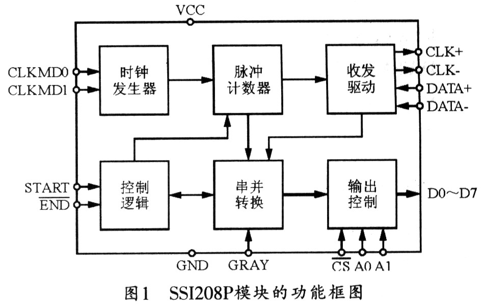
The SSI208P module has completed the conversion and encapsulation of the SSI interface and the parallel port. Therefore, reading the SSI interface data becomes similar to the operation of reading data from A/D, D/A or memory, which is very simple. The SSI208P module converts data from Gray code format to BCD code format. Its communication rate can be configured to 250 kHz, 500 kHz, 1 MHz and 2 MHz. When the communication rate is configured to 2 MHz, the system is 16-bit precision encoder. The data update rate is not less than 100 kHz, so it can meet the needs of high-speed servo control systems.
1.2 SSI208P pin configuration The SSI208P interface module is packaged in DIP28, and its pin arrangement is shown in Figure 2. The function of each pin is as follows:
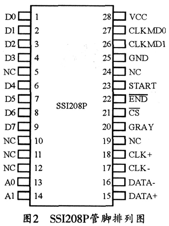
CLKMDl, CLKMD0: SSI clock frequency setting port, where 00 is 250 kHz, 0l is 500 kHz, 10 is 1 MHz, and 11 is 2 MHz;
START: Start command, start conversion on rising edge;
END: Conversion end status query, low is the end of conversion;
CS: encoder data output selection terminal;
GRAY: Data format conversion selection, l is the conversion of Gray code to BCD code output. 0 is the BCD code output;
D0~D7: 8-bit data output parallel port;
A1, A0: output data high and low bit selection end, 00 is the lowest eight bits, 11 is the highest eight bits;
CLK+, CLK one: SSI encoder clock signal;
DATA+, DATA one: SSI encoder data signal;
VCC, GND: power supply, power ground;
NC: Empty feet.
1.3 SSI208P control timing The control timing of SSI208P is shown in Figure 3. The SSI encoder data transceiving process can generally be initiated on the START rising edge. Within 125 ns of the START level rise, the SSI208P module begins to send a frame of synchronous clock pulses to the encoder. The number of pulses is determined by the accuracy of the encoder, and the conversion end pin END goes high. During the transmission pulse, the pin END remains high, the conversion ends, and the END pin level becomes low. The encoder data can be read in parallel from DO~D7, and each bit is read eight times and controlled by Al and AO. The upper and lower bits of the output data, 00 means that the lowest eight bits are read, and 11 means that the highest eight bits are read. For a 16-bit encoder, you only need to read it twice (A1 and AO are 00, 01 respectively), and you can read up to 32 bits of data. After the encoder parallel data read is complete, the START pin should be deasserted to prepare for the next conversion.

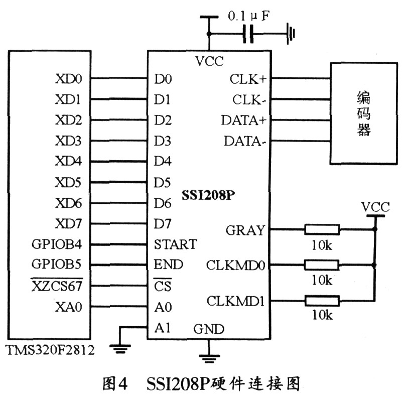
1.4 SSI208P-based interface design The SSI208P module can greatly simplify the software and hardware design of the SSI encoder interface for microcontroller, DSP, PCI04 and other controllers. A typical application based on the DSP processor TMS320F2812 is given below. Figure 4 shows the hardware connection schematic diagram of the DSP processor TMS320F2812 and SSI208P module. The encoder is a single-turn 16-bit absolute angle encoder. The output data format of the encoder is Gray code. The eight-bit data bus of the SSI208P module is connected to the lower eight-bit data line of the TMS320F2812. Since the encoder used is 16 bits, only one address line is needed to distinguish the upper eight bits and the lower eight bits of the encoder data, and the external address chip select pin/XZCS67 can be used as the external chip select signal of the SSI208P, and Use the general-purpose IO port GPIOB4 to control the SSI208P module startup, and use the general-purpose IO port GPIOB5 to perform the SSI208P module conversion end status query. The CLKMDO and CLKMD1 should be connected with pull-up resistors and the SSI208P module synchronous clock frequency should be configured to 2MHz. Pulling the GRAY pin high, the SSI208P module can convert the Gray code data output from the encoder into a BCD code.
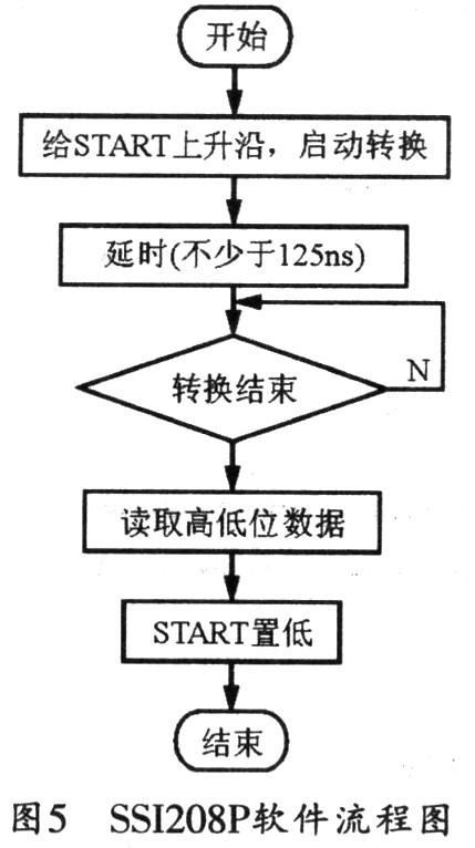
It can be seen from the control timing diagram of the SSI208P module that the startup conversion control and data reading operation of the SSI208P module are relatively simple, and the software flow is shown in FIG. 5.
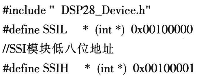
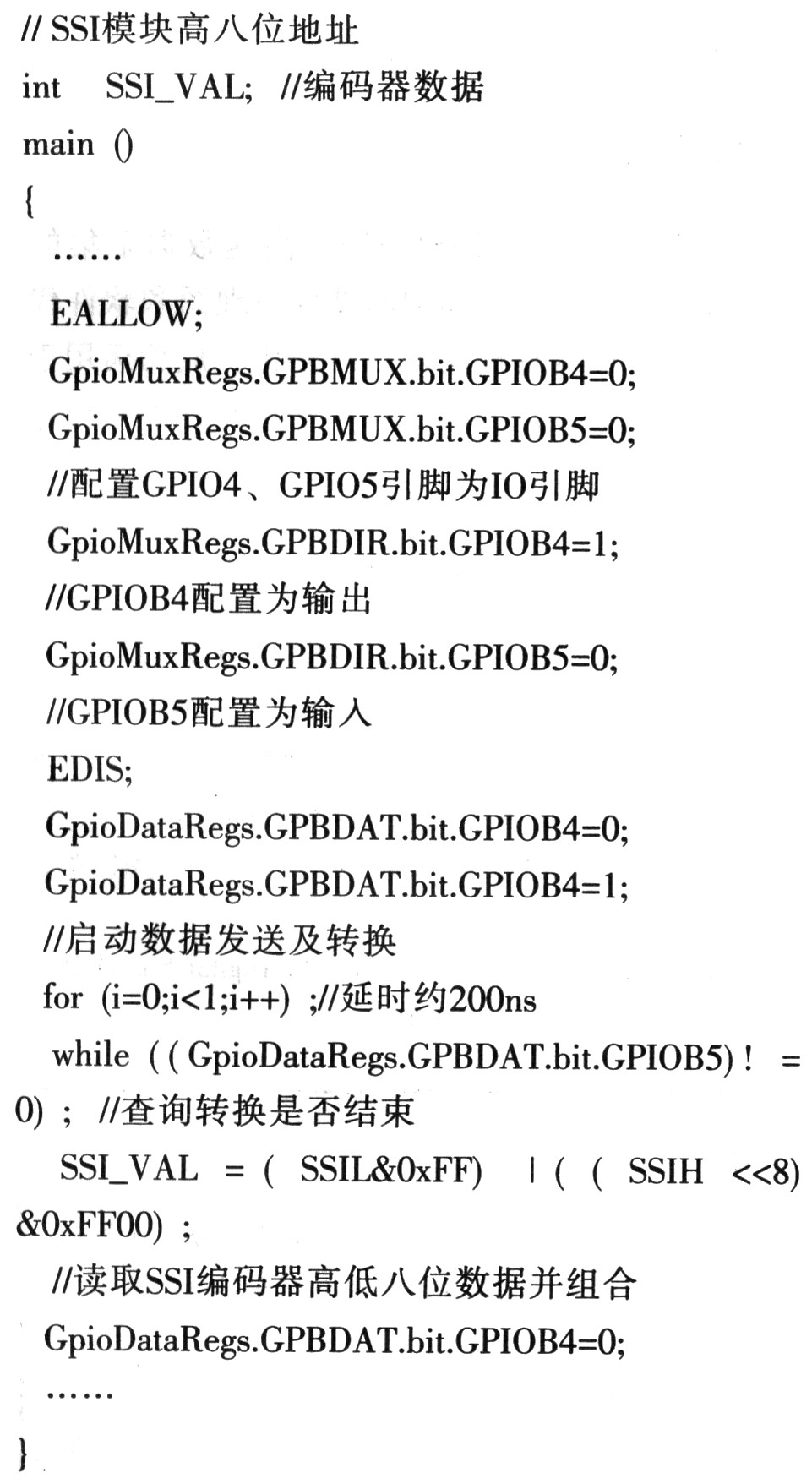
Corresponding to the hardware design of Figure 5, the corresponding software code of the DSP processor TMS320F2812 is as follows:
2 SSI encoder universal asynchronous serial acquisition scheme
2.1 Introduction to SSI208S Module SSI208S module can be used to convert SSI synchronous serial data into universal asynchronous serial data (RS-232, RS-422 or RS-485 can be used), PC and industrial computer commonly used in industrial control field. DSP, MCU and other control systems are generally equipped with a universal asynchronous serial interface. Therefore, the SSI encoder can be easily connected to these control systems using the SSI208S module.
2.2 SSI208S pin configuration The SSI208S interface conversion module is packaged in DIP24, and its pin arrangement is shown in Figure 6. The function of each pin is as follows:

VCC, GND: power supply, power ground;
CLKMDl, CLKMD0: same as SSI208P;
232TX: RS-232 data transmission;
232RX: RS-232 data reception;
MODE: working mode setting port;
A1, A0: address setting end;
GRAY: data format conversion selection, 1 is to convert Gray code to BCD code output, 0 is BCD code output;
CLK+, CLK one: SSI encoder clock signal;
DATA+, DATA one: SSI encoder data signal;
CAP: Connect decoupling capacitors;
NC: Empty feet.
The pin MODE can be used to set the working mode of the SSI208S module: 0-active mode, 1-inquiry mode. In the active working mode, the module periodically sends location information to the host; in the inquiry mode, the host first sends inquiry information (address information) to the module, and then the SSI208S module returns location information to the host. The address setting pins A1 and A0 can set the address information of the module, so that multiple SSI encoders can be connected to the asynchronous serial bus, and O_0 to 1-1 correspond to addresses 0 to 3, respectively.
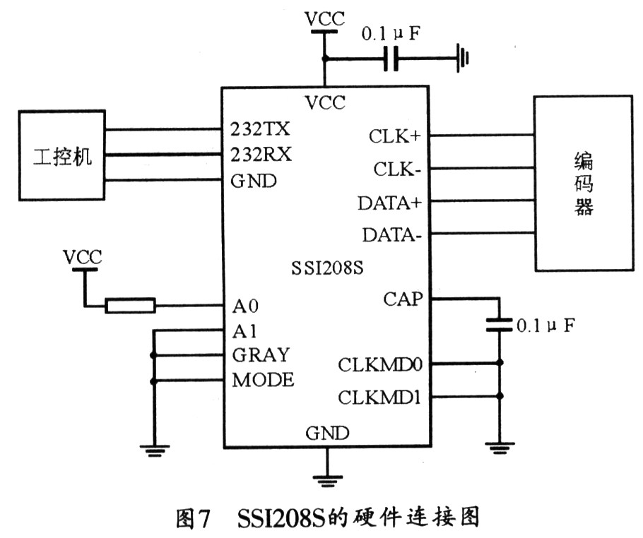
2.3 Application of SSI208S The SSI208S module can also greatly simplify the software and hardware design of the SSI encoder interface for microcontroller, DSP, PCI04 and other controllers. The following is an application example of the industrial computer and SSI208S module. The hardware connection principle is shown in Figure 7. The encoder accuracy is 16 bits, and the BCD code output is used. The universal asynchronous serial communication rate is 115200 bps, and the encoder SSI communication rate. Set to 250 kHz and use the interrogation mode, the encoder address is set to 0x01.
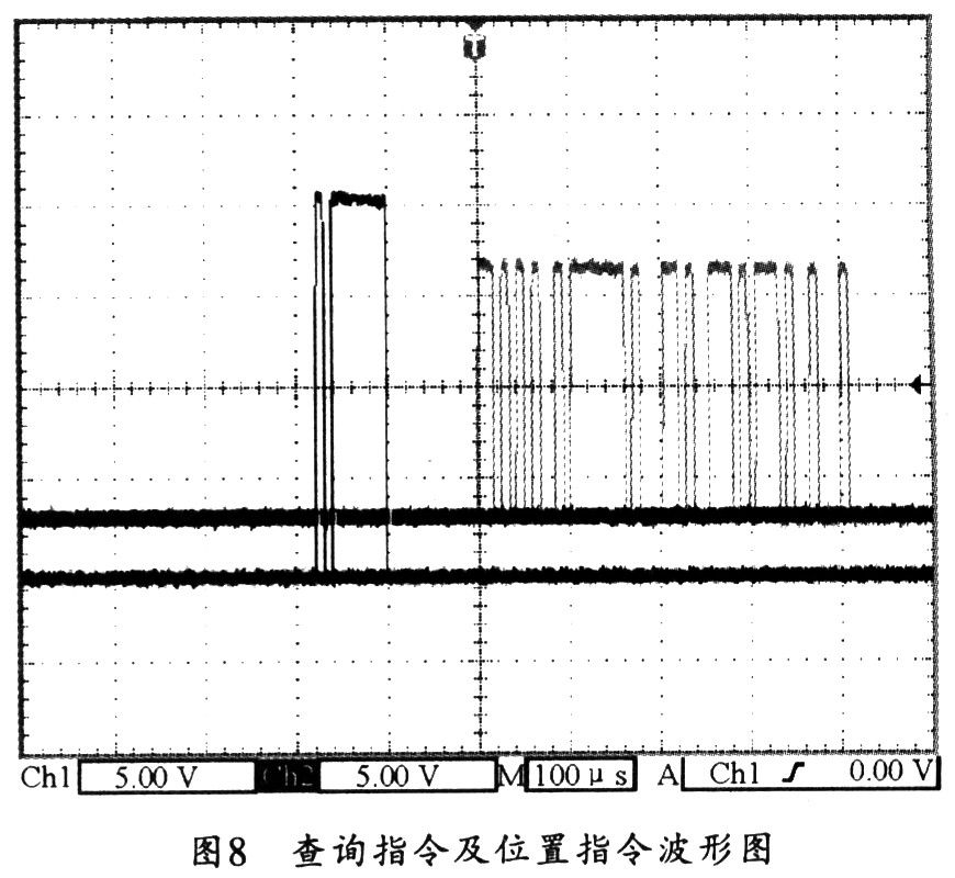
After the industrial computer sends the address information 0x01 to the SSI module, the SSI module will return 0xAA 0x01 0x23 0x34 0x57. 0xAA is the packet start flag, 0xol is the encoder position information, 0x23 and 0x34 are the encoder position information, and 0x57 is the check information. Figure 8 is a waveform diagram of the query command captured by the oscilloscope and the position command returned by the SSI module. It can be seen from the figure that the SSI module will send the encoder position information to the host after 0.1 ms after the IPC issues the inquiry command, which includes the synchronous serial communication time of the encoder. Setting a higher communication rate can reduce this lag time. In the query mode working mode, the data update period of the encoder is about 0.6ms. It can be seen that the data update rate is greater than 1600 Hz, which can meet the requirements of high-speed servo control systems.
3 Conclusion This article provides two SSI encoder high-speed data acquisition implementation, and provides detailed hardware schematics and software code. At present, these two modules have been commercialized and successfully applied to the fire control subsystem of an in-vehicle system, and are very stable and reliable in operation.
Double Ended Pogo Pin,Handheld Device Pogo Pin,Double Head Pogo Pin
Pogo pin CO.,Ltd , http://www.nspogopin.com