
How to choose the appropriate architecture, circuits and components that meet the target system specifications and standards? These are determined by the circuit satisfying the performance required by the system in terms of efficiency, bandwidth, and accuracy while satisfying the requirements for safety isolation.
This article discusses the impact of system architecture choices on power supply and control circuit design and system performance.
Isolation framework
Our concern is that you need to safely control the flow of energy from the AC source to the load based on the commands provided by the user. This problem is illustrated in the high-level motor drive system diagram in Figure 1 for the following three power domains: reference, control, and power.
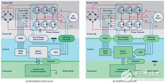 Figure 1. Isolation architecture in motor control system
 The safety requirement is that the user's given circuit must be electrically isolated from the dangerous voltage on the power circuit. The architectural decisions depend on whether the isolation barrier is placed between a given and control circuit or between the control and power circuits. Introducing isolation barriers between circuits can affect signal integrity and increase costs.
The isolation of analog feedback signals is particularly difficult because traditional transformer methods suppress the DC signal components and introduce nonlinearities. Digital signal isolation at low speeds is fairly simple, but it is very difficult at high speeds or when low latency is needed, and it consumes a lot of power. Power isolation in systems with 3-phase inverters is particularly difficult because there are multiple power domains connected to the power circuit. The power supply circuit has four different domains that need to be functionally isolated from one another; therefore, the high-side gate drive and winding current signals need to be functionally isolated from the control circuit, even though both may be co-located with the power ground.
Non-isolated control architecture
Non-isolated control architectures have a common ground connection between the control and power circuits. This way the motor control ADC can get all the signals in the power circuit. When the motor winding current flows into the low-side inverter arm, the ADC samples at the midpoint of the center-based PWM signal. The driver of the low-side IGBT gate can be a simple, non-isolated type, but the PWM signal must be isolated from the gates of the three high-side IGBTs by having functional isolation or level shift conversion. The complexity caused by the isolation between command and control circuitry depends on the end application, but usually involves the use of separate systems and communication processors. The architecture that simple processors can manage front panel interfaces and send speed commands on slow serial interfaces is acceptable in home appliances or low-end industrial applications. Due to the high bandwidth requirements of the command interface, non-isolated architectures are less common in high performance drives for robotics and automation applications.
Isolated Control Architecture
The isolated control architecture has a common ground connection between the control and command circuits. This allows very tight coupling between the control and command interfaces, and a single processor can be used. The isolation issue goes to the power inverter signal, which brings a series of different challenges. Gate drive signals require relatively high-speed digital isolation to meet the inverter's timing requirements. Due to the very high voltages present, magnetically or optically coupled drivers perform well in inverter applications where isolation is extremely demanding. The requirements for DC bus voltage isolation circuits are modest because of the low dynamic range and bandwidth required. Motor current feedback is the biggest challenge in high performance drives because it requires high bandwidth and linear isolation. Current transformers (CTs) are a good choice because they provide isolated signals that can be easily measured. CT is nonlinear at low currents and does not transmit DC levels, but is widely used in low-end inverters. CT is also used in high-power inverters with non-isolated control architectures, because the sampling of shunt resistors in these cases will result in too much loss. Open-loop and closed-loop Hall-effect current sensors measure AC signals and are therefore more suitable for high-side drivers but are subject to misadjustment. Resistive shunts provide high-bandwidth, linear signals with low offset but need to match high-bandwidth, low-skew isolation amplifiers. In general, the motor control AD ​​C can directly sample the isolated current signal, but the alternative measurement architecture described in the next section can transfer the isolation problem to the digital domain and can significantly improve performance.
Inverter feedback using isolated converters
A common way to improve the linearity of an isolation system is to move the ADC to the other side of the isolation barrier and isolate the digital signal. In many cases, this requires the use of a series ADC with a digital signal isolator. Because of the special high frequency requirements for motor current feedback and the need to quickly respond to drive protection, a Σ-Δ ADC can be chosen. The Σ-Δ ADC is equipped with a linear modulator that converts the analog signal into a one-bit stream, followed by a digital filter that reconstructs the signal into high-resolution digital words.
The advantage of this method is that two different digital filters can be used:
â— Slower for high-fidelity feedback,
â— Another low-fidelity fast filter is used to protect the inverter.
In Figure 2, a winding shunt is used to measure the motor winding current and an isolated ADC is used to transmit a 10 MHz data stream on the isolation barrier. The sinc filter can present high resolution current data to the motor control algorithm, which calculates the inverter duty cycle required to apply the required inverter voltage. Another low-resolution filter detects current overload and sends a transition signal to the PWM modulator in the event of a fault. The sinc filter frequency response curve explains how the proper parameter selection can cause the filter to suppress the PWM switching ripple in current sampling.
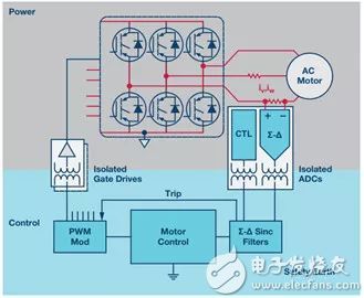 Figure 2. Isolated current feedback
 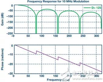 Figure 3. Sinc filter frequency response
 Power output isolation
The common problem with both control architectures is the need to support multiple isolated power domains. If each domain requires multiple offset tracks, it is more difficult to achieve. The circuit of Figure 4 can generate +15 V and –7.5 V for gate drive and the +5 V for ADC power, all in one domain, while using only one transformer winding and two pins per domain . Use a transformer core and bobbin to create dual or triple supplies for four different power domains.
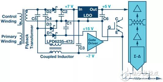 Figure 4. Isolated Power Circuits for Gate Drive and Current Feedback Converters
 The author
Aengus Murray, Manager, Motor and Power Control Applications, Automotive, Energy, and Sensors, Analog Devices, Inc. He is responsible for the entire ADI signal chain product for industrial motors and power control. Murray holds a bachelor's and doctorate in electrical engineering from the University of Dublin, Ireland, and has more than 30 years of experience in the power electronics industry.
Original Bulb Lamp With Housing
The original projector bulb lamp with housing is installed with the original brand factory projection lamp, providing bright and clear pictures, visual appreciation, high quality and worry-free service. It can be directly put into the projector, the installation is simple, and no reassembly is required.
Original Bulb Lamp With Housing,Buy Projector Lamp,Projector Lamp Light,Original Projector
Shenzhen Happybate Trading Co.,LTD , https://www.happybateprojectors.com