
An important feature of any solar panel is its ability to achieve peak power output at a relatively constant operating voltage (VMP), independent of the level of illumination (see Figure 1). The LT3652 2A battery charger takes full advantage of this feature to maintain the peak operating efficiency of the solar panel by implementing input voltage regulation (patent pending). The input voltage regulation circuit will reduce the battery charging current when the available solar power is insufficient to meet the power requirements of an LT3652 battery charger. This will reduce the load on the solar panel to maintain the solar panel voltage at VMP, thereby maximizing the output power of the solar panel. This method of achieving peak solar panel efficiency is known as Maximum Power Point Control (MPPC).
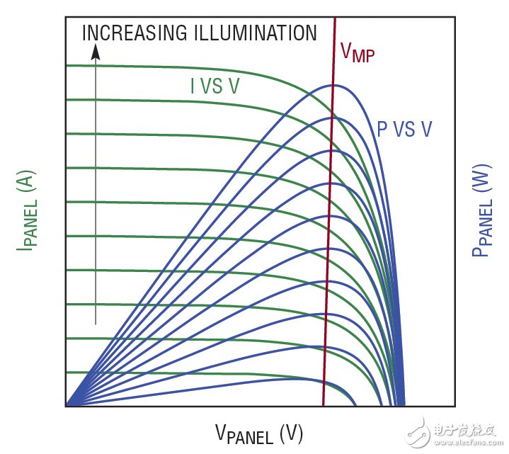
Figure 1: Solar panels produce maximum power at a specific output voltage (VMP), which is relatively independent of the level of illumination. The LT3652 2A battery charger maximizes the solar panel's output power by adjusting the solar panel input voltage to VMP.
Although the MPPC can optimize the efficiency of the solar panel during low illumination, the power conversion efficiency of the battery charger will be poor when the power level is low, resulting in a decrease in the total power transmission efficiency from the solar panel to the battery. This article will show you how to improve battery charger efficiency by using a simple PWM charging method that forces the battery charger to release energy in the form of a burst when the power level is low.
Use current monitor status pin to indicate low power conditions
The /CHRG current monitor status pin on the LT3652 is responsible for indicating the state of the battery charge current and is used here to control the PWM function. This pin is pulled low when the charger output current is greater than C/10 (ie 1/10 of the programmed maximum current) and is high impedance when the output current is below C/10.
During low illumination, the input regulation loop reduces the charger's output current to less than C/10, causing the /CHRG pin to become high impedance. The “state change†function of this status pin is used to disable the IC by triggering an input undervoltage lockout (UVLO) circuit whose falling threshold is at a higher than the input regulation voltage VIN(REG). As a response to the charger deactivation, the solar panel voltage will climb within the UVLO hysteresis until the UVLO rise threshold is reached, at which point the charger is re-enabled at full power. The charger will then provide a charging current until the input voltage regulation loop deactivates the charger again. This cycle is repeated continuously to produce a charger output consisting of a series of high current bursts that maximize the efficiency of the charger and the efficiency of the entire solar charger system at any level of illumination.
High efficiency lithium ion battery charger
Figure 2 shows a solar panel with a low-power PWM function to a 3-cell Li-Ion battery charger. The charger uses a 17V input regulation voltage (a common VMP for "12V system" solar panels) that is set using resistor dividers R4 and R5 on the VIN_REG pin. Maintaining the operating voltage of a typical 12V system solar panel at its 17V rated VMP voltage produces nearly 100% solar panel efficiency, as shown in Figure 3. The low power PWM function is implemented with M1, R6, R7 and R8. As shown in Figure 4, the addition of a PWM circuit can significantly improve efficiency when the battery charge current is less than 200mA.
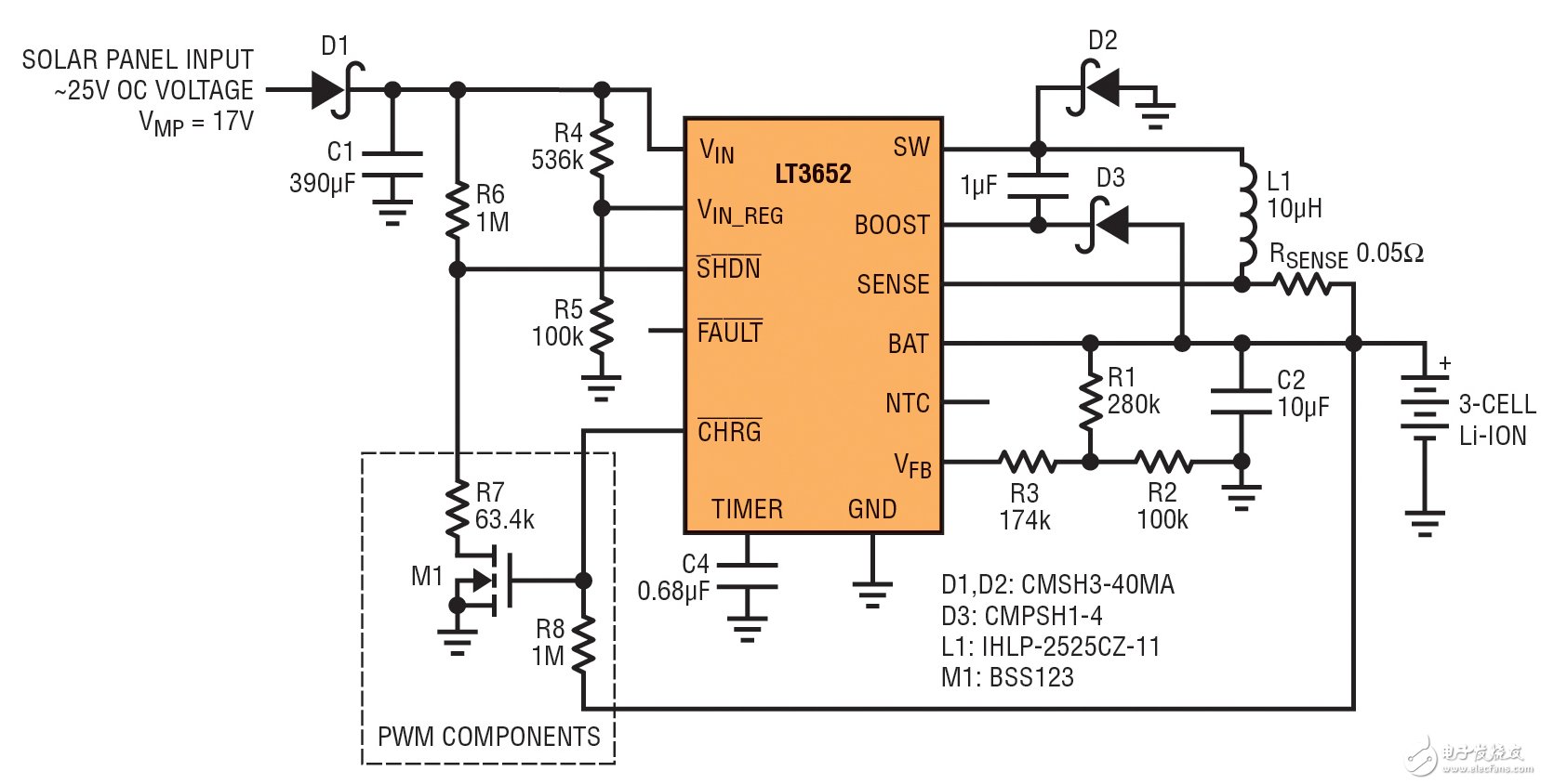
Figure 2: 17V VMP Solar Panel to 3-Cell Li-Ion Battery (12.6V) 2A Charger 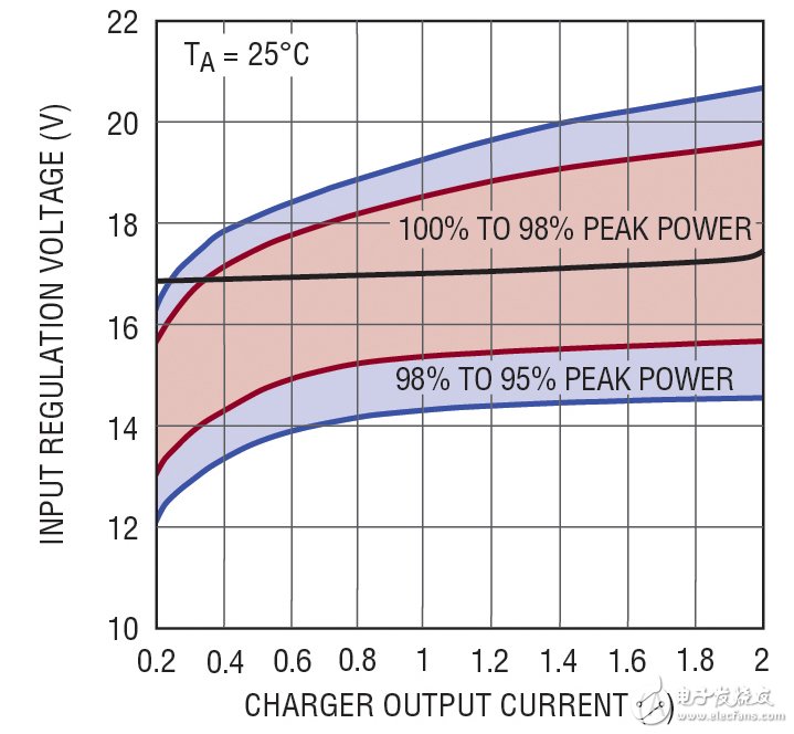
Figure 3: Typical “12V System†(VMP = 17V) Solar Panel Efficiency 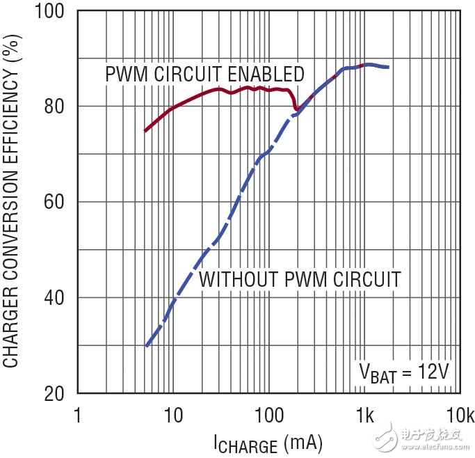
Figure 4: Efficiency of the circuit shown in Figure 2
Robot Vacuum Cleaners With Mopping
Robot Vacuum Cleaners With Moppin,Robot Vacuum Cleaner With Bluetooth ,Robot Vacuum Cleaner With Gyroscope,Cleaner Robot Ultrasonic Cleaner
NingBo CaiNiao Intelligent Technology Co., LTD , https://www.intelligentnewbot.com