
This article describes the solution for an FPGA-based wireless charger receiver system. The wireless charger receiver strictly follows the latest WPC Qi standard. The receiver system consists of an analog module and an FPGA module. The analog module consists of discrete components, including a full-bridge rectifier module, V/I detection and AD control modules, and a DC-DC module. The FPGA module acts as a digital core with embedded communication modules, control modules, computing modules, and transceiver modules. It uses the Verilog language and state machine to program the FPGA. Finally, through testing and verification, the wireless charger receiver works great on wireless charger transmitters from several major OEMs.
Background
With the rapid development of wireless charger technology and the increasing number of smartphone users being plagued by various charging cables, convenient and easy-to-use wireless chargers will be widely accepted and adopted. There are currently three different wireless charger standards: WPC (Qi), PMA and A4WP.WPC Qi standards are more commonly used in smartphone applications. Many smartphone OEMs have now introduced wireless charger solutions that support the WPC standard. This article will focus on the WPC standard wireless charger receiver solution and its relationship to a detailed FPGA-based system architecture.
2. Overview of WPC standards
The WPC Qi standard provides a detailed description of the wireless charger system, including communication and transport protocols. Power is always transferred from the charging pad to the mobile device. The charging board contains a subsystem called a power transmitter (consisting of a primary coil), and the mobile device contains a subsystem called a power receiver (consisting of secondary coils).
Figure 1 illustrates the basic system configuration. As shown, the power transmitter consists of two main functional units, the power conversion unit and the communication and control unit. The control and communication unit adjusts the converted power to the level requested by the power receiver. The power receiver consists of a power pick-up unit and a communication and control unit.
The power receiver is located on the mobile phone, so the next step will be to introduce the power receiver system and explain the solution for the FPGA-based wireless charger receiver.
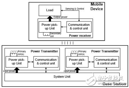
Figure 1: Basic System Configuration
3. Overview of FPGA-based power receiver systems
According to the WPC Qi standard, the power receiver system will include a power pick-up unit and a communication and control unit. The example will detail a receiver solution that fully satisfies the requirements of the WPC Qi standard. Figure 2 shows the architecture of an FPGA-based power receiver system.
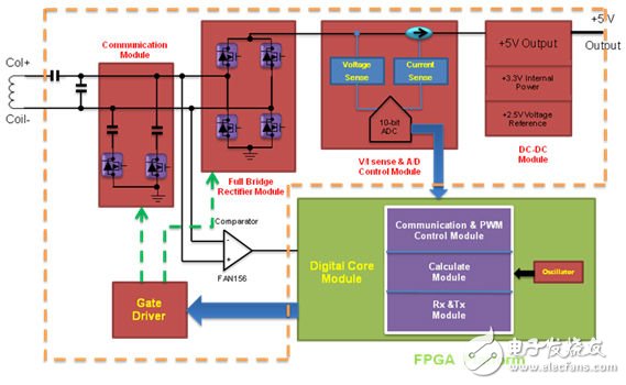
Figure 2: System Architecture
As shown in Figure 2, the receiver system consists of two subsystems, one is an analog module and the other is a digital module. The analog module consists of discrete devices, including full-bridge rectifier modules, V/I detection and AD control modules, communication modules, and DC-DC modules. Digital modules are built into the FPGA and are written in Verilog. The digital core module can be divided into three main sub-modules: the first is the communication and PWM control module, the second is the calculation module, and the third is the Rx and Tx (receiver and transmitter) modules. These modules are described in more detail below.
4. Analog module
The secondary coil is the source of power for the analog module; the primary and secondary coils form a complete coreless resonant transformer. Through electromagnetic coupling, the alternating magnetic field will generate an alternating current source in the secondary coil, and then the full bridge rectifier converts the alternating current to direct current. Figure 3 shows the schematic of a partial analog module.
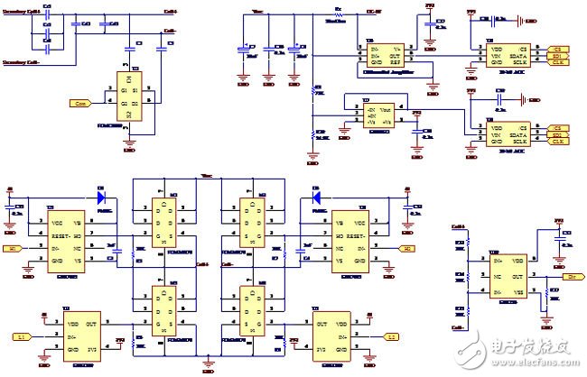
Figure 3: Schematic of a partial analog module
Mono panel,High Quality Mono panel,Mono panel Details, Yangzhou Bright Solar Solutions Co., Ltd.
Yangzhou Bright Solar Solutions Co., Ltd. , https://www.cnbrightsolar.com