
1 Introduction
Because humanoid robots have the basic shape of humanoids, they can do a lot of work instead of people in real life. Therefore, the research on humanoid robots has practical value, and all countries are investing huge human and material resources for research and development. The humanoid robot has the mechanical structure requirement of multiple degrees of freedom, so it is necessary to complete the turning motion through the motor for each joint of the robot. This places high performance requirements on motor drive control. This paper proposes a humanoid robot control system based on STM32 single-chip microcomputer, which can drive and control the 16-way servos required for robot joints at the same time.
2 hardware solutions
The hardware part of the control system is divided into five modules, and the hardware system module diagram is shown in Figure 1.
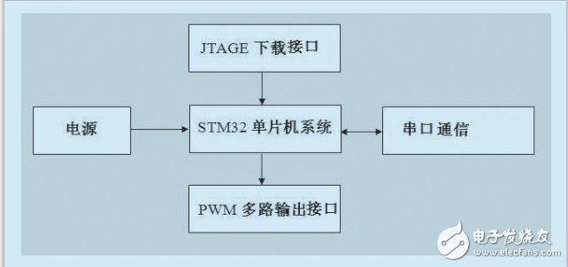
Figure 1 hardware system module block diagram
The main controller adopts STM32F103xB enhanced series of single-chip microcomputers, which use high-performance ARM CortexTM-M3 32-bit RISC core, operating at 72MHz, built-in high-speed memory (128K bytes of flash memory and 20K bytes of SRAM). Enhanced I/O port [2]. These features make the STM32F103 series of microcontrollers ideal for use in control systems for small humanoid robots. Due to the limited body shape of the humanoid robot, we used the STM32F103 series of small SMD32F103CBT6 in the STM32F103 series when designing the servo control board. In order to get a smaller steering gear control Circuit Board, as shown in Figure 2.

Figure 2 Steering gear control board physical map
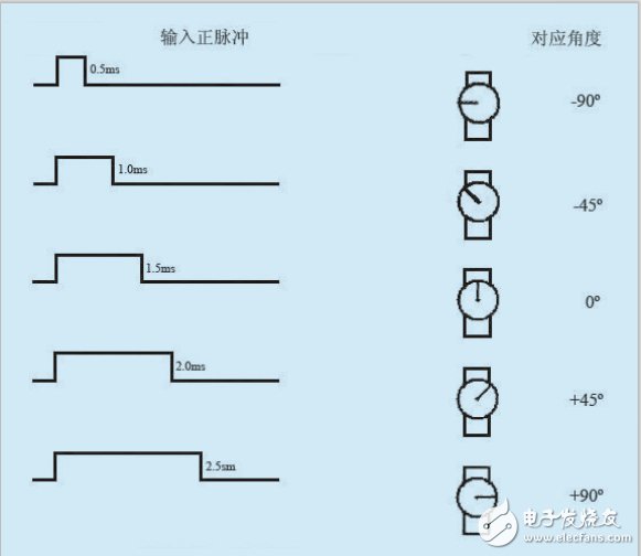
Figure 3 Schematic diagram of steering gear control
In order to realize the action control of a humanoid robot with a multi-degree of freedom complex structure, a steering control panel with a large number of control points is required. Since the angle control of the steering gear is PWM waveform output, when the output pulse width of the IO port of the single chip microcomputer changes, the steering wheel angle of the steering gear changes, as shown in Fig. 3 [3], so in the circuit design of the steering gear control board, Make full use of the STM32 microcontroller's IO port number and the technical advantages of PWM output [4]. A total of 16 steering gear control ports have been designed to ensure that 16 robot joints operate simultaneously. The servo drive IO interface is distributed on both sides of the PCB board for easy insertion and removal.
In the control of the steering gear, there is an easy problem that is the steering rudder problem. This problem generally occurs when a common battery is used as the main power source of the robot system, such as a multi-section AA-type nickel-cadmium or nickel-hydrogen battery connected in series to form a robot-powered main power source. The reason is that these batteries cannot provide long-term stable and continuous high current at their rated voltage due to limitations in capacity and discharge capacity. When the multi-way servo of the humanoid robot works at the same time, the voltage of the output of the ordinary power supply will be rapidly reduced, which will result in insufficient power supply to the steering gear, and eventually the abnormality of the steering wheel will occur, causing the rudder phenomenon of the robot when performing the action.
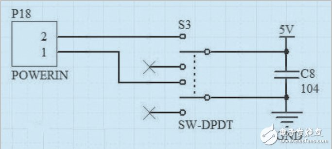
Figure 4 Control signal 5V power supply schematic

Figure 5 Schematic diagram of 6V servo drive power supply
Therefore, the humanoid robot control circuit designed by us uses a lithium polymer model battery with a capacity of 2200 mAh and a rated voltage of 11.1V as the main power source. It is divided into 5V control signal power supply and 6V servo drive power supply, as shown in Figure 4. In order to ensure the large current required for multi-way servos to work at the same time, the lithium polymer battery has a strong continuous discharge capability, and the 120W 12A high-power step-down module [5] is selected to stabilize the power supply of the robot. At +6V, the peak discharge current is 12A, as shown in Figure 5. The optocoupler is used to isolate the IO port control signal and the servo drive signal of the single chip microcomputer to improve the anti-interference ability of the control signal. The schematic diagram of the IO port circuit design of the steering gear is shown in Figure 6. This solves the problem of abnormal vibration of the steering wheel caused by the power supply being pulled down due to the simultaneous operation of the multi-way servo.

Figure 6 Schematic diagram of the servo IO port circuit
When the servo control board is initially powered up, all IO ports will simultaneously input an unordered PWM signal, causing huge current consumption in an instant. When the servo control board is tested by the experiment, the peak current of a single IO port can reach 1.5A or more. Therefore, when 16 servos are initially powered on and the PWM signal is initially applied, the total current will reach 24A or more, which greatly exceeds the limit supply current of the large-capacity DC step-down module, causing the power circuit to enter overcurrent protection. The machine control circuit will not be able to enter normal operation. In order to solve this problem, when the STM32 MCU is powered on, first let only the IO ports 1 and 2 output the PWM signal, and then let the IO port 3 and 4 output initialize the PWM signal, and finally let the IO ports 15 and 16 in this order. Output PWM signal. This ensures that when the IO port is initialized, only two PWM signals are simultaneously input. When the robot is in normal operation, the number of servos at the same time does not exceed six, that is, the peak current of 6 IO simultaneous outputs is 9A, which is lower than the maximum output current of the high-power buck module by 12A, so the limit of the whole circuit during operation The current is less than 12A. Finally, the hardware requirements for the stable operation of the steering gear control board are achieved.
3 software part design
The software of the humanoid robot control system is divided into two modes: debug mode and normal mode.
Debug mode: The robot is powered on by default and is in response to the host computer signal. In this mode, the host computer controls the robot online through the RS232 serial port, which can precisely adjust the angle of a single servo, arrange a single execution of the process action, execute all the process actions, and display the current robot's code analysis. value. The working interface of the debug mode is shown in Figure 7.
Normal mode: The robot completes the full set of program actions after commissioning.
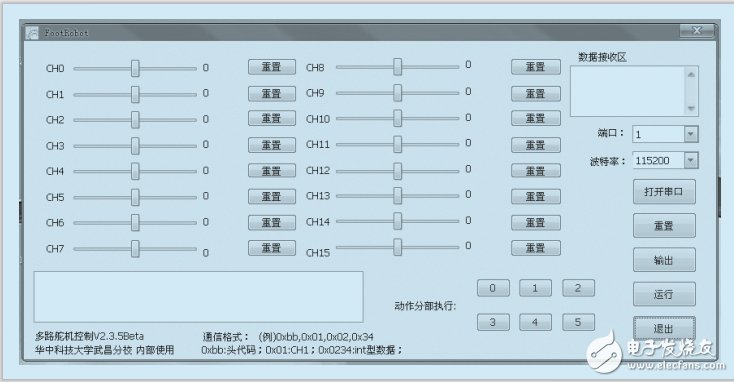
Figure 7 PC debug mode work interface
In order to implement software control, the timing rotation mechanism of the multitasking module is adopted [6]. A total of three module tasks have been established: Task 0 is used to resolve the conversion of software code values ​​sent to the task to the PWM output. Task 1 is used to call each set of action codes, and continuously send the obtained software values ​​to task 0. Task 2 is a serial port processing task, which analyzes the data sent by the serial port to perform mode conversion and response. The program flow chart is shown in Figure 8.
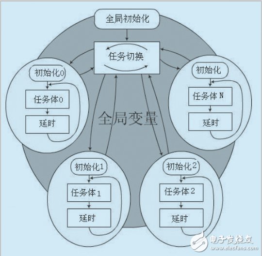
Figure 8 program flow chart
4 system debugging effect
When designing the walking gait of the humanoid robot, the robot's own weight is 2.53Kg and the height is 42cm. Therefore, the output of the robot's foot and arm should not be too large, otherwise it will cause the robot to walk. The center of gravity is too offset, causing the robot to tip over. Therefore, when designing the sole of the robot, the contact area with the ground is appropriately increased. The size of the sole is 8.5 & TImes; 15 cm, and the frequency of the movement of the foot is accelerated, and an additional weight is added to the foot to enhance the robot. The stability of the walking process, the gait of walking is shown in Figure 9. The robot's walking gait is coordinated and won the second prize in the 2012 China Robot Competition.
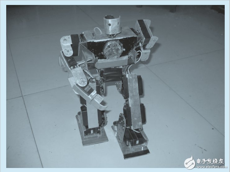
Figure 9 12-degree-of-freedom humanoid robot
Walking action
5 Conclusion
In this paper, the humanoid robot control system based on STM32 microcontroller can flexibly control the 16-way high-torque steering gear. Through the high-power step-down power supply module, the DC voltage required for the simultaneous operation of the 16-way steering gear can be obtained. The walking action of the humanoid robot can be used as a reference for college students to carry out robot technology innovation.
PDU Power Socket
PDU Power Socket be with any type plug,could be selected to be with USB ports,Internet ports,Phone ports,overload protection and with or without switch.
PDU Power Socket can be set into furniture and office furniture like table,cabinet and so on.It will be easily to use the charging for Phone and home appliance.
Specifically, We have our own design and production team for USB Circuit Board design and produce
PDU Power,Us PDU Power Strip,PDU Power Outlets,United Power PDU
Dongguan baiyou electronic co.,ltd , https://www.dgbaiyou.com