
The Arduino expansion board is called Shield, and the Raspberry Pi expansion board is called HAT (Hardware Attached on Top), which means a hardware board attached to the top of the Raspberry Pi. Let's take a look at an open source Raspberry Pi expansion board from scratch, temporarily named Raspberry Pi ICA HAT.
Raspberry Pi ICA HAT
Demand analysis
The original intention of designing HAT is to provide basic display and user input functions for Raspberry Pi, and to bring out hardware interfaces such as UART, I2C, SPI, etc., to easily connect other modules, and also as a user's entry board for learning Raspberry Pi hardware programming ( Starter Board). The configuration of ICA HAT is as follows:
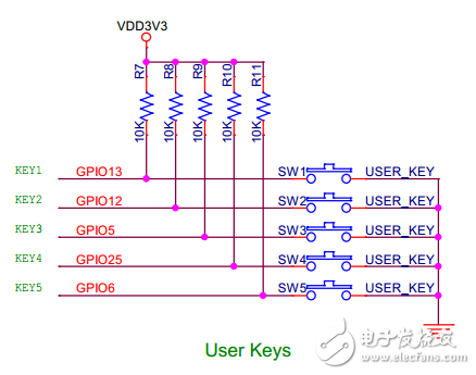
1. User button x5, can be used as up, down, left and right and "OK" button;
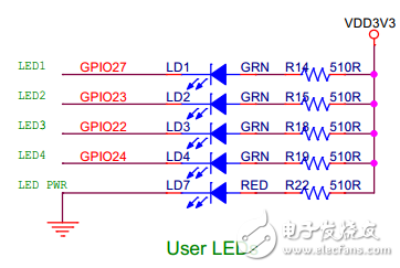
2. User LED x4, to achieve basic indication function, and a power indicator LED;
3. Active buzzer x1, providing alarm function;
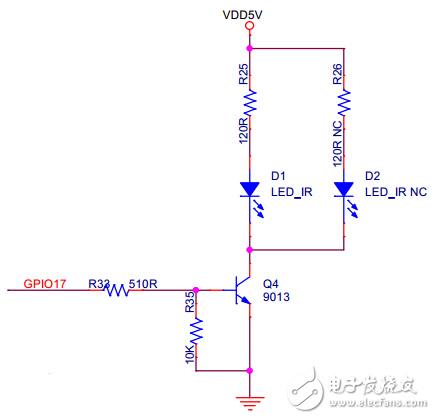
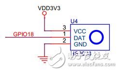
4. Infrared transmitting tube x2, infrared receiving head x1, realize infrared remote control function;
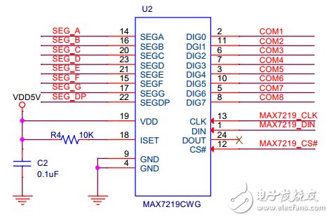
5. Seven-segment digital tube x2, realize 8-bit digital display, driven by MAX7219 chip with SPI interface;
6. I/O and power extensions are numbered.
After setting the requirements, the first thing to consider is the structural problem. The design of this example is for the Raspberry Pi 2B model, and it is also compatible with the B+ model of the first generation. The picture below shows the mechanical structure of the Raspberry Pi 2B/B+:
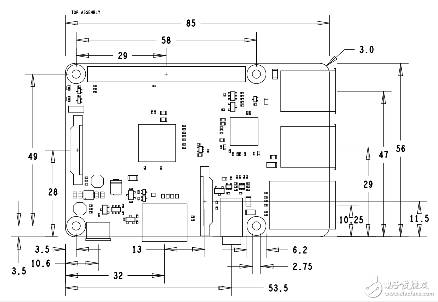
For the mechanical structure of the Raspberry Pi, both full length and half length HAT can be designed. The full-length board is the same size as the Raspberry Pi frame, but because the Raspberry's USB and RJ45 connectors are high, you need to be aware of whether the device at the bottom of the area will be in contact with the connector.
The half-length board contains only four areas of screw holes.
Both boards are connected to the header pins on the motherboard via a 2.54mm spacer and are secured to the motherboard by four M2.5 copper posts or screws. As shown below.
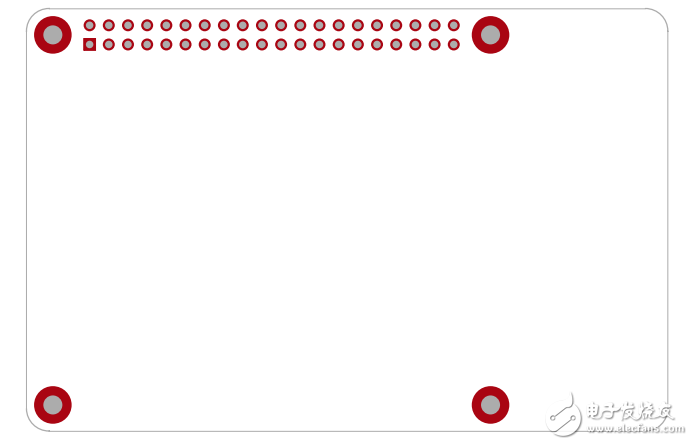
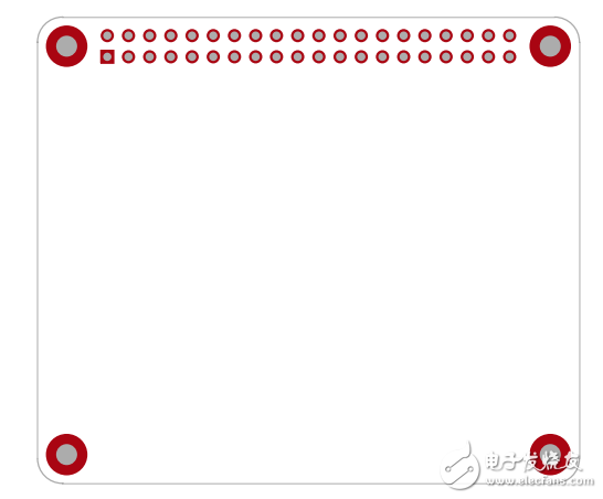
Figure full length HAT and half length HAT
The two sizes of HAT that have been designed have been stored on GitHub, and the reader can design on this basis. 
Electronic enthusiasts June "Embedded Technology Special Issue", more quality content, download now
After analyzing the mechanical structure, the next thing to consider is the I/O resource allocation. The Raspberry Pi 2B/B+ I/O includes two SPI interfaces, two I2C interfaces, and a UART interface. There are no hardware PWMs and ADCs available. Also, I2C0 is used as the IDPROM interface for reading the HAT board information, which is not available to the user. SPI1 is also called SPI_AUX in the CPU. Currently, the Linux driver is not perfect, but it can be called through the pigpo library. As shown below:
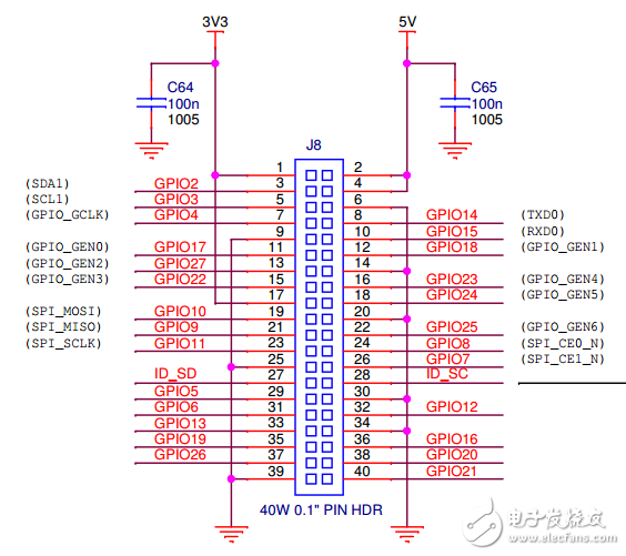
In this example, SPI0, I2C1, and UART0 are pulled out to the pin headers. The MAX7219 uses SPI1 control and uses GPIO as the chip select. Other functions assign GPIOs arbitrarily according to the wiring.
2. Hardware design and production
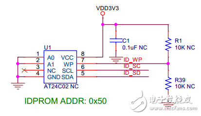
After the requirements analysis is completed, the hardware design begins. The rabbit uses the Cadence 16.6 tool. The schematic tool is OrCAD Capture CIS and the PCB tool is Allegro PCB Editor. The first is IDPROM, which connects an EEPROM to the Raspberry Pi's I2C0. This part of the circuit is reserved and will not be installed during actual production (the actual non-welded device is indicated by NC).
The user LED uses GPIO sink current control, and the LED illuminates when IO is low.
The button part is realized by the level of the left side of the GPIO detection button, and the level is high when the button is released, and is pressed low. Hardware debounce is not added here and software implementation is required.
The infrared transmitting tube needs a large current, so the infrared LED is driven by a GPIO controlling the NPN transistor, and the infrared tube is turned on when the level is high. Only one LED can be soldered and used, and two LEDs can be used to enhance the infrared signal.
The infrared receiver uses the integrated receiver HS0038, which can work at 3.3V and use a GPIO to receive infrared signals.
The active buzzer also needs a large current, and is driven by a triode like the infrared tube. When the GPIO is high, the buzzer sounds.

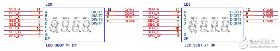
The digital display uses two 4-digit 7-segment digital tubes (common cathodes, counting 8 decimal points) and is driven by the MAX7219 chip. The MAX7219 provides up to eight 8-bit displays. Here, the MAX7219's segment codes A~DP are simultaneously connected to two digital tubes in sequence to display the contents of each bit. The digital selection signal of the MAX7219 is connected to the common terminals of the two digital tubes.
The MAX7219 is connected to the Raspberry Pi via SPI. Since only control does not need to read the information, DOUT can be disconnected. The chip is powered by 5V. In the strict sense, the SPI should use the 5V level. The 3.3V level of the Raspberry Pi can also be controlled normally, but it is recommended to set the level conversion circuit.
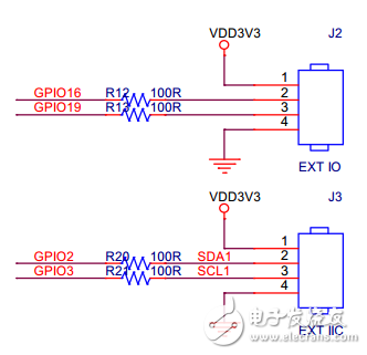
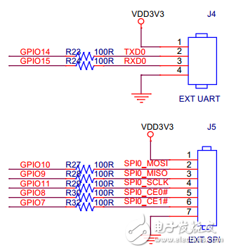
Finally, the interface expands the pin header, and the serially connected 100 ohm resistor acts as a current limiting protection. Each interface provides a 3.3V supply and GND.
The ICA HAT PCB uses a cheap double panel (the rabbit only needs 50RMB for 10 PCBs), and the layout is required.
According to the general user's usage habits, the digital tube is placed on the upper part of the board (the most prominent position), and the button is placed in the lower right corner of the board (the left-handed friend can be placed on the left side). The infrared transceiver part and the IO interface are neatly arranged on the sides of the board to prevent blocking and convenient wiring. Others such as LEDs and buzzers can be placed in the middle of the board.
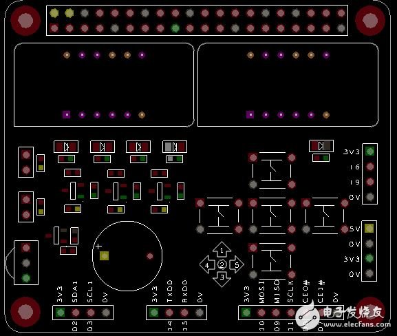
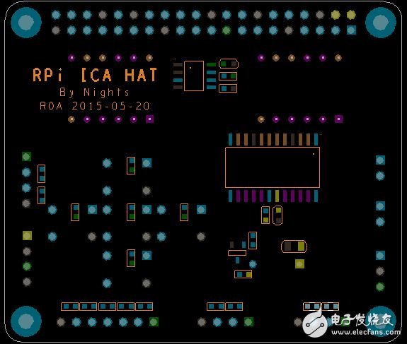
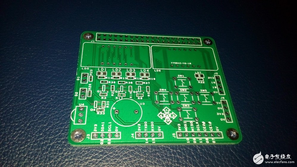
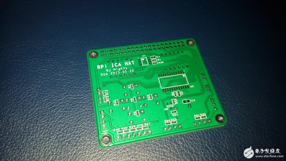
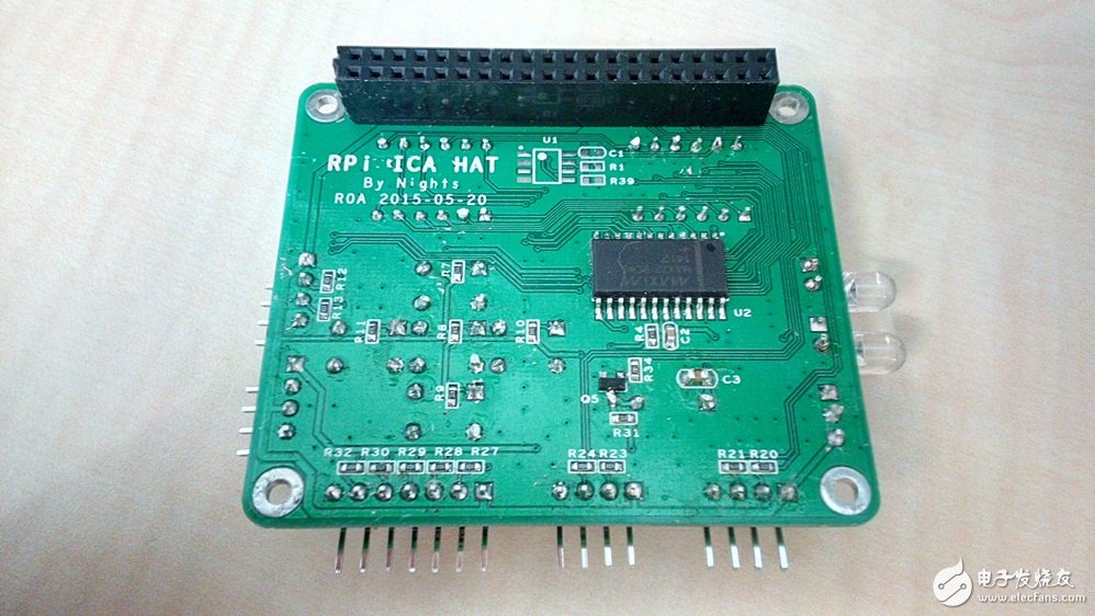
The designed PCB files can be exported to the PCB manufacturer for the Artwork and Drill files. The domestic manufacturers will generally accept the engineering files in the Altium Designer and Protel formats, but they are actually converted into light paintings. Production. The manufacturer will also provide free testing to ensure that the circuit does not have a short circuit, etc. The following picture shows the produced PCB:
After the PCB is produced, the device is soldered. If it is machine soldering, it is necessary to provide a solder mask file for the production of steel mesh and an assembly file for the machine patch.
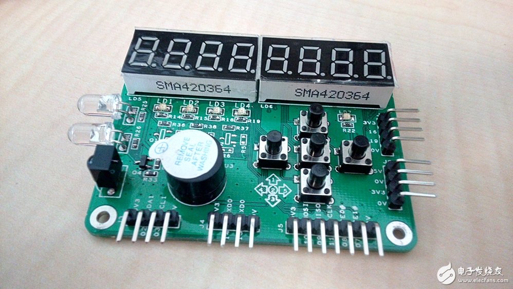
Here, due to the small amount of devices, the rabbit is hand soldered. Soldering can be done with solder chips that are more difficult to pin-bond, then solder devices with lower heights, and finally soldered higher in-line devices. The connector and the digital tube can be soldered at the end. The picture below shows the board that was hand soldered, which we call PCBA:
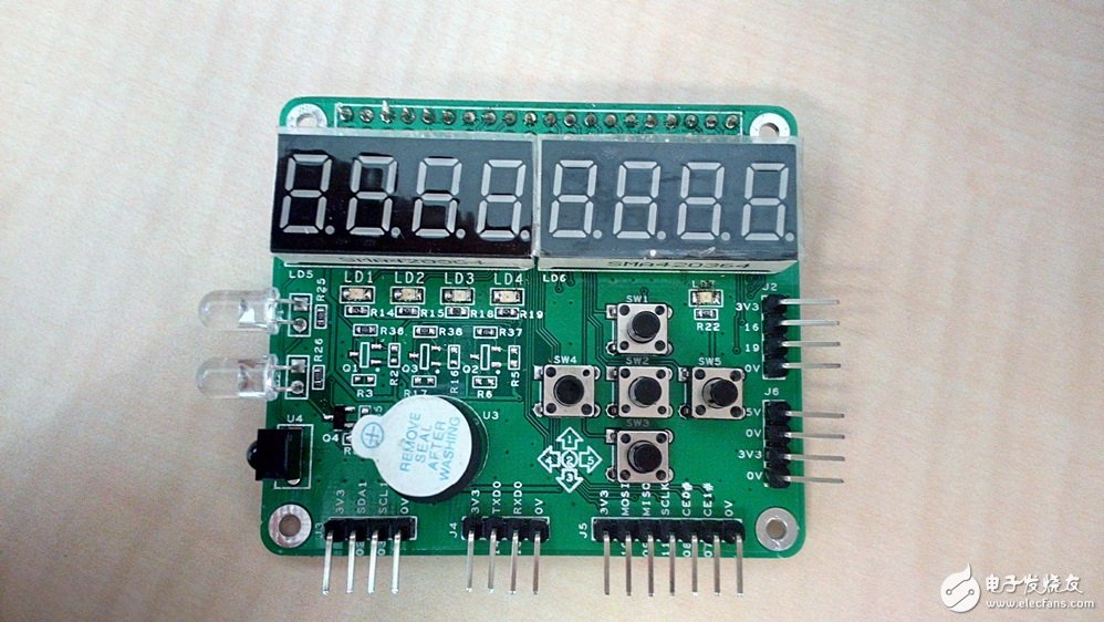
It should be noted that after the soldering is completed, it is necessary to test whether the circuit is short-circuited, especially the short circuit of the power supply, and then the power-on test. Otherwise, it may not only burn the HAT board, but also damage the Raspberry Pi motherboard.
Hybrid Solar System,Hybrid Solar System Price,Solar Hybrid Power Systems,Lithium Battery Solar System
Wuxi Sunket New Energy Technology Co.,Ltd , https://www.sunketsolar.com