Definition and background
In an RF transmission system, the standing wave ratio (SWR) is used to measure the transmission efficiency of an RF signal from a power transmission source through a transmission line and ultimately to a load. For example, the power amplifier is connected to the antenna through a length of transmission line.
SWR reflects the ratio of incident wave to reflected wave. The higher the SWR, the lower the efficiency of the transmission line and the higher the reflected energy, which may cause damage to the transmitter and reduce the emission efficiency. Since SWR is usually expressed in terms of voltage ratio, it is also called voltage standing wave ratio (VSWR).
VSWR and system efficiency
An ideal system is to transfer energy 100% from the power source to the load, which requires the characteristic impedance of the source impedance, transmission line, and other connectors to exactly match the load impedance. Since there is no interference in the ideal transmission process, the signal AC voltage remains the same across the transmission line.
In practical systems, impedance mismatch will cause some of the power to be reflected to the source (like an echo). The reflection causes superposition and destructive interference, thereby generating voltage peaks and troughs on the transmission line at different times and at different distances. VSWR is used to measure these voltage changes, which is the ratio of the highest voltage to the lowest voltage anywhere on the transmission line.
Since the voltage in an ideal system remains the same, its VSWR is 1.0, which is usually expressed as 1:1. When a reflection occurs, the voltage changes and the VSWR increases, for example, by making the VSWR 1.2 or 1.2:1.
Reflected energy
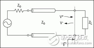
When the incident wave reaches the boundary, for example, when the load reaches the load through the lossless transmission line (Fig. 1), part of the energy is transferred to the load and the other part of the energy is reflected back. The reflection coefficient represents the ratio of the incident wave to the reflected wave:
Γ = V-/V+ (Formula 1)
In the formula, V- is a reflected wave, and V+ is an incident wave. The relationship between VSWR and voltage reflection coefficient (Γ) is:
VSWR = (1 + |Γ|)/(1 – |Γ|)(å¼2)

Figure 1. The transmission line circuit illustrates the impedance mismatch between the transmission line and the load.
The reflection at the boundary is Γ, the incident wave is V+, and the reflected wave is V-.
The VSWR can be measured directly using the SWR meter, and RF test instruments such as a vector network analyzer (VNA) can be used to measure the reflection coefficients of the input port (S11) and the output port (S22). S11 and S22 are equivalent to the reflection coefficient 输入 of the input port and output port. The mathematical model of VNAs can also be directly used to calculate and characterize VSWR.
The return loss of the input and output ports can be calculated by the reflection coefficient S11 or S22:
RLIN = 20log10|S11| dB(å¼3)
RLOUT = 20log10|S22| dB(å¼4)
The reflection coefficient can be calculated from the characteristic impedance and load impedance of the transmission line as follows:
Γ = (ZL - ZO) / (ZL ​​+ ZO) (Equation 5)
Where ZL is the load impedance and ZO is the characteristic impedance of the transmission line (Figure 1).
VSWR can also be represented by ZL and ZO. Substituting Equation 5 into Equation 2, you can get:
VSWR = [1 + |(ZL - ZO)/(ZL + ZO)|]/[1 - |(ZL - ZO)/(ZL + ZO)|] = (ZL + ZO + |ZL - ZO|)/ (ZL + ZO - |ZL - ZO|)
If ZL > ZO, |ZL - ZO| = ZL - ZO
then:
VSWR = (ZL + ZO + ZL - ZO) / (ZL ​​+ ZO - ZL + ZO) = ZL / ZO. (Formula 6)
If ZL < ZO, |ZL - ZO| = ZO - ZL
then:
VSWR = (ZL + ZO + ZO - ZL) / (ZL ​​+ ZO - ZO + ZL) = ZO/ZL. (Equation 7)
We note that the VSWR mentioned above is a ratio relative to 1, for example VSWR is 1.5:1. There are two special cases for VSWR: 1 and 1:1. When the load is open, the VSWR is ∞:1. When the load and the transmission line characteristic impedance are completely matched, the VSWR is 1:1.
VSWR is defined as the standing wave generated by the transmission line itself:
VSWR = |VMAX|/|VMIN|(8)
Among them, VMAX is the maximum value of the standing wave voltage on the transmission line, and VMIN is the minimum value of the standing wave voltage on the transmission line. The maximum value is generated by the superposition of the incident wave and the reflected wave in the same direction. therefore:
VMAX = V+ + V- (Formula 9)
The minimum value is generated by the inverse superposition of incident and reflected waves:
VMIN = V+ - V- (Formula 10)
Substituting Equation 9 and Equation 10 into Equation 8, you can get:
VSWR = |VMAX|/|VMIN| = (V+ + V-)/(V+ - V-) (Equation 11)
Substituting Equation 1 into Equation 11 yields:
VSWR = V+(1 + |Γ|)/(V+(1 - |Γ|) = (1 + |Γ|)/(1 – |Γ|)(å¼12)
Equation 12 is equal to Equation 2 herein.
VSWR detection system
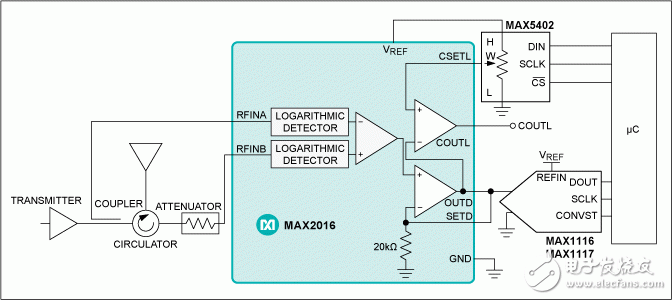
The MAX2016 is a dual-channel log detector/controller that is used with circulators and attenuators to monitor the VSWR/return loss of the antenna. The MAX2016 can output the difference between two power detectors.
The MAX2016 and MAX5402 digital potentiometers and the MAX1116/MAX1117 ADCs form a complete VSWR monitoring system (Figure 2). The digital potentiometer acts as a voltage divider for the MAX2016 output reference voltage, and the internal voltage reference provides a typical 2mA current that sets the internal comparator threshold voltage (CSETL). An alarm output is generated when the output voltage is above or below the threshold voltage (COUTL). The MAX1116 ADC operates from 2.7V to 3.6V, and the MAX1117 ADC operates from 4.5V to 5.5V. The ADC can also provide a voltage reference using the MAX2016, which monitors the VSWR of the antenna together with the microcontroller.

Figure 2. The supporting ADC is used to build the VSWR real-time monitoring system.
Configure the comparator output (COUTL) alarm threshold with an external digital potentiometer.
to sum up
This guide, SWR or VSWR, is a measure of transmission line defects and efficiency. VSWR is related to the reflection coefficient. Higher ratios indicate a more serious mismatch, while 1:1 is a perfect match. The match or mismatch depends on the maximum and minimum amplitude of the standing wave. SWR is the ratio of transmitted energy to reflected energy. MAX2016 is used to illustrate how to create a system to monitor the antenna's VSWR.
Small Solar Panel,Small Solar Panels,4W Small Solar Panel,Small Solar Panel For Poly
Yangzhou Bright Solar Solutions Co., Ltd. , https://www.solarlights.pl
