
Accelerate dimming frequency PWM for precise LED dimming
Whether the LED is driven via a buck, boost, buck/boost or linear regulator, the most common thread connecting each driver circuit is the need to control the output of the light. Today, there are only a few applications that require simple functions to turn on and off, and most need to fine tune the brightness from 0 to 100%. Currently, for brightness control, the two main solutions are linearly adjusting the LED current (analog dimming) or switching the drive current from 0 to the target current value at high frequencies that are undetectable to the naked eye (digital adjustment) Light). Using pulse width modulation (PWM) to set the cycle and duty cycle may be the easiest way to implement digital dimming because the same technique can be used to control most switching converters.
PWM dimming can be used to match accurate color light
In general, analog dimming is easier to implement because the output current of the LED driver changes proportionally to the control voltage, and analog dimming does not cause additional electromagnetic compatibility (EMC) / electromagnetic interference (EMI) potential frequencies. problem. However, most of the reasons for PWM dimming are based on the basic characteristics of LEDs, ie the displacement of the emitted light is proportional to the average drive current (Figure 1). For monochromatic LEDs, the wavelength of the main light wave changes, and in the case of white LEDs, the relative color temperature (CCT) changes. For people's naked eyes, it is difficult to detect the change of nanometer wavelength in red, green or blue LEDs, especially when the intensity of light is also changing, but the color temperature change of white light is easier to detect. Most white LEDs contain a wafer that emits blue-spectrum photons that emit photons in various visible ranges after striking the phosphor coating. At lower currents, phosphorescence dominates and deflects light toward yellow; at higher currents, the LED emits more blue light, causing the light to deflect toward blue and also produce a higher CCT. For applications that use more than one white LED, the CCT difference between two adjacent LEDs can be significant and visually unpleasant, and this concept can further extend the source of multiple monochromatic LED rays. Once more than one light source is present, any CCT difference that occurs between them can be dazzling.
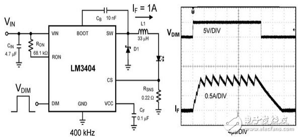
Figure 1 LED driver and waveform using PWM dimming
The LED manufacturer specifies the magnitude of the drive current in the current characteristics table of its product, which only guarantees the product's dominant wavelength or CCT under these specific current conditions. The advantage of PWM dimming is that there is no need to consider the intensity of the light, and it also ensures that the LED emits the color desired by the designer. This precise control is especially important for red, green, and blue (RGB) applications because these applications mix light of different colors to produce white light.
From the perspective of driver ICs, analog dimming faces serious challenges in output current accuracy. Almost all LED drivers add some form of serial resistor to the output to detect current, and the selected current sense voltage VSNS produces a coordinated effect that allows the circuit to maintain a high signal-to-noise ratio (SNR). While maintaining low power consumption, the error caused by the tolerance, offset, and delay in the driver is relatively fixed. To reduce the output current in a closed loop system, the VSNS must be lowered, but the accuracy of the output current will decrease until the absolute value of VSNS equals the error voltage. Finally, the output current becomes uncontrollable. The target output current will not be determined or guaranteed. In general, in addition to improving the accuracy of PWM dimming, the linear control of low-order light output is also stronger than analog dimming.
Dimming frequency is inversely proportional to contrast
For PWM dimming signals, each LED has a defined response time. Figure 2 shows three different delays. The higher the delay, the lower the contrast that can be achieved (a measure of light intensity control). .
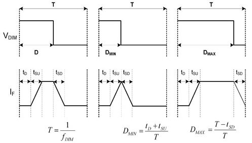
Figure 2 dimming delay
The amount of time tD in Fig. 2 represents the propagation delay between the start of the rising of the logic signal VDIM and the start of the increase of the output current by the LED driver, and the amount of time tSU represents the time required for the output current to be converted from 0 to the target current, as for the time. The amount tSD represents the time required for the output current to transition from the target current back to zero. In most cases, the lower the dimming frequency fDIM, the higher the contrast, because these fixed delays only occupy a small portion of the dimming period TDIM. The lower limit of the dimming frequency fDIM is about 120 Hz. If it is lower than this frequency, the eyes can no longer mix the pulses into a continuous continuous light. The upper limit depends on the minimum contrast requirement, and the contrast is generally expressed as the reciprocal of the minimum on time.
CR=1 / tON-MIN: 1
tON-MIN =tD+tSU
Applications such as machine vision identification and industrial inspection often require higher PWM dimming frequencies, primarily because high-speed cameras and sensors respond much faster than human eyes. In such applications, the purpose of high-speed on and off of the LED source is not to reduce the average light output, but to synchronize the light output with the capture time of the sensor or camera.
A GFCI outlet receptacle is different from conventional receptacles.
In the event of a groud fault, a GFCI will trip and quickly stop the flow of electricity to prevent serious injury.
How does LED Trip indicators work?
Indicator: 2 LED Trip Indicators (Red & Green)
• Red-The device needs attention. the device is engineered to conduct a self-test internally every 2 minutes to ensure the protection is on. If the device fails the test, the red light is on to signal that the device should be replaced
• Green-The device has passed self-test and working properly
Regular GFCI UL,Receptacle GFCI,GFCI Outlet with UL943,GFCI Receptacle
Hoojet Electric Appliance Co.,Ltd , https://www.hoojetgfci.com