
Abstract: This paper proposes a design method of vehicle remote monitoring system based on heterogeneous multi-core system. It uses dual Nios II processor to realize system control and image processing. At the same time, hardware coprocessor module is designed to realize image preprocessing and compression work. The wireless network sends monitoring information. It effectively improves the acquisition, processing, compression and transmission speed of the system and realizes real-time monitoring of remote vehicles.
Keywords: heterogeneous multi-core; Nios II; Sobel; moving target detection; JPEG; general wireless packet service
This article refers to the address: http://
0 Introduction With the increasing familyization of automobiles, car theft has occurred frequently. According to incomplete statistics, the number of car stolen in China is as high as 100,000 per year. Aiming at the shortcomings of existing automobile monitoring and anti-theft system, such as noise pollution, high false alarm rate, instability, high power consumption, this design proposes a vehicle remote monitoring system based on heterogeneous multi-core system, using two Nios II soft cores as the main The processor forms a dual-core system, and the hardware DSP processes the IP as a coprocessor of the dual-core system to form an embedded system of heterogeneous multi-core. A high-precision CMOS camera is used to capture the video image of the monitored area, and the output is monitored by VGA in real time, and a series of processing is performed on the image data to determine whether there is any foreign matter in the monitoring area. Thereby reducing the false alarm rate, the stability and real-time performance of the monitoring system are further improved.
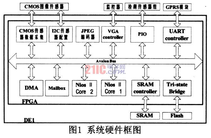
1 Design scheme The system adopts the DEl development platform provided by Altera Corporation. The detection sensor group includes: vibration and acceleration inclination sensor to complete the measurement of acceleration, inclination and vibration energy parameters in the vehicle monitoring system. The image acquisition of the CMOS image sensor is monitored in real time on the VGA port after being preprocessed by the FPGA image, and the image is compressed by the JPEG encoder. System control and image processing moving target detection using dual-core Nios II. The RF module completes GPRS wireless communication, and sends image data and monitoring information to the monitoring center and the user's mobile phone through the GPRS network. The hardware block diagram of the system is shown in Figure 1.
2 system hardware design
2.1 Heterogeneous multi-core system In the design, due to a large number of real-time image data operations, the calculation speed of a CPU can not meet the requirements, and even there are erroneous results. Here two NIOS II are used to form a dual-core system, and the hardware DSP is designed to process IP. As a coprocessor of the dual-core system, work together to complete the task.
As the main control core, Nios II Corel runs the UCOS II operating system, manages the scheduling of all tasks, completes the acquisition of vehicle sensors, the calculation of acceleration dip vibration, and the transmission of SMS MMS. As a secondary core, Nios II Core2 completes the acquisition of video images of two consecutive frames and performs real-time moving target detection algorithms. The communication between the dual cores is realized by sharing the On Chip Memory through the Mailbox IP core. At the same time, the Sobel operator boundary detection hardware image preprocessing module and JPEG image compression IP are designed as the coprocessor of the dual core system to form a heterogeneous multicore embedded system. The block diagram is shown in Figure 2. Since SDRAM is used as a buffer for video images, Corel is run in SRAM here. Core2 runs in Flash, and reads and writes data and stacks are stored in SRAM.

2.2 Automotive sensor acquisition board design The automotive sensor signal acquisition board uses AD company's acceleration sensor ADXL202AQC to measure the X/Y direction acceleration, tilt angle and vibration value of the car. The sensor acquisition system block diagram is shown in Figure 3. The ADXL202AQC is fabricated by MEMS technology and is a low-cost, low-power, single-chip integrated dual-axis accelerometer. It operates from a single source of 3 to 5.25V and operates at less than 6mA. It can measure dynamics in the range of 0~5kHz and ±2g. Or static acceleration, the resolution is 2mg at 60Hz, and can be output in the form of digital and analog signals.
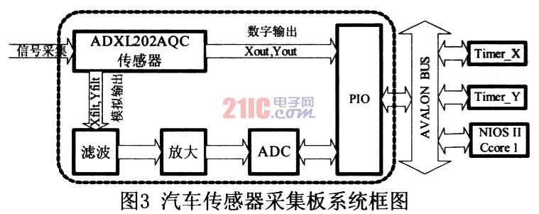
The ADXL202AQC collects the biaxial acceleration value, outputs the digital quantity through Xout and Yout, and outputs the digital signal with different duty ratio corresponding to the acceleration value. The two digital signals are collected into the SOPC system through the PIO port, and the Timer X and Timer Y timers are used. To calculate the exact acceleration value, the Nios II Corel determines the acceleration dip value of the three-dimensional space for the two acceleration values ​​and the gravitational acceleration value.
At the same time, Xfilt and Yfilt output the analog semaphore of the acceleration, and the signal range is controlled to 10~200Hz through the bandpass filter. The small amount of vibration can pass through, and the ADC is converted into the SOPC system through the PIO port after amplification and ADC conversion. The value is calculated to obtain the amplitude of the vibration.
2.3 Image acquisition, processing and compression system image acquisition Terasic's TRDB-D5M camera, the actual pixel 2592H × 1944V, the color array is RGB (red, green and blue) mode, the maximum data transmission speed is 96Mb under 96MHz clock s, VGA (640 × 480) output frame rate up to 70f / s, built-in 12-bit ADC converter, 3.3V single power supply, I / O port voltage range 1.7 ~ 3.1v. Fully meet the system requirements, the system takes the signal collected by the camera through the Soble operator edge detection preprocessing, and simultaneously monitors it through the VGA port, and then sends the image data to the Nios II Core 2 for moving target detection. When the moving target is detected in the monitoring area, The image is JPEG-compressed to facilitate GPRS data transmission. The following describes each module.
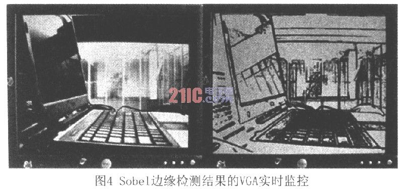
2.3.1 Sobel operator edge detection preprocessing Image edges often carry most of the information of an image and are one of the most basic features of the image. Image edge detection is the basic steps of image processing, image analysis, pattern recognition and computer vision. The correctness and reliability of the results will directly affect the machine vision system's understanding of objective things. The system uses the classical Sobel operator edge detection algorithm to weight the gray of the left and right and upper and lower fields of the image pixel, and performs edge detection based on the principle of reaching the extreme value at the edge point. The amount of data processed by the algorithm is large, and it will be slower to achieve real-time requirements through software programs. The system uses Verilog to design hardware modules to achieve this function. The image acquired by the CMOS camera is preprocessed, and the edge detection result is sent to VGA real-time monitoring (as shown in FIG. 4), and the image data is calculated by Nios II Core 2 for calculation. In the design, 3 × 3 pixel blocks and a large number of multiply-add operations are needed. Here, Altem's Megafuncation library is used. For example, the ALTSHIFT_TABS shift register buffers three rows of pixels, and then sends each buffer line to the ALTMULT ADD multiply block. .
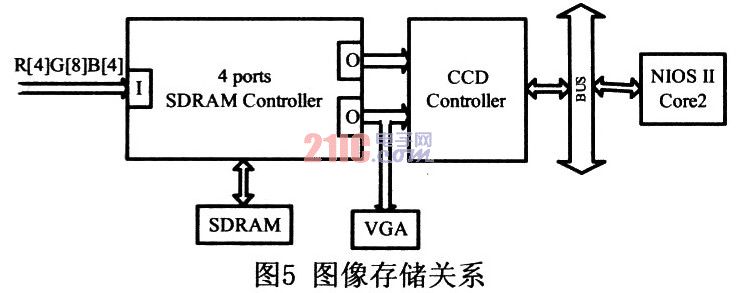
2.3.2 Moving target detection module The video image is a two-dimensional projection of a three-dimensional image. When the three-dimensional image changes, the two-dimensional image will also change accordingly. By calculating the change between consecutive frames in real time, when there is a moving target This will cause a frame difference. The system adopts the 10-level frame difference method, which can set the alarm level according to the requirements of detection sensitivity, and adopt different weights for different ranges of the monitoring area to improve the judgment accuracy of the moving target. Due to the high real-time performance required by the frame difference algorithm, a large number of image signals collected continuously should be processed immediately, otherwise the test results will be affected. The system uses the processor NIOS II Core2 to complete the work separately. SDRAM is used as the image signal buffer captured by the camera. Here, the 4 Ports SDRAM Controller-IP core provided by Teraisc is used to store the converted RGB signal in the SDRAM in 16 bits. Two consecutive image signals are stored in the SDRAM and simultaneously transmitted to the NIOS II Core2 through the two output ports (ports) of the 4 Ports SDRAM Controller IP. One of the output ports is connected to the VGA port. The image storage relationship is shown in Figure 5.
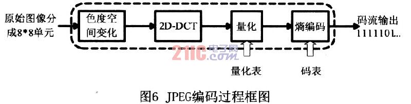
2.3.3 JPE6 image compression IP core design In order to facilitate GPRS image transmission, the image needs to be compressed. Here, the image is compressed by JPEG compression standard, and the JPEG image compression DSP module is designed by Verflog as the system coprocessor. Mounted on the system Avalon bus. The steps of the compression algorithm in the JPEG standard include two-dimensional DCT, quantization, entropy coding, and the like. The coding process block diagram is shown in Figure 6.
When designing the encoder, the image is first divided, the RGB signal is YCbCr, the YCbCr signal is 2D-DCT, and the ZigZag scan is used to convert the two-dimensional data into one-dimensional data with continuous coefficients, according to the JPEG organization. The quantization table quantizes and compresses the data, and finally performs VLC coding and Haffman coding on the quantization result to obtain a compression result. The core part is the 2D-DCT conversion. The design process is introduced here: the discrete cosine transform is an orthogonal transform, and the 2D-DCT transform formula is as follows:
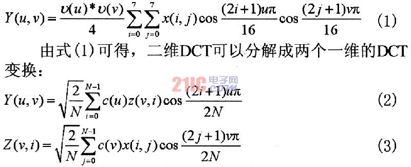
The system uses matrix multiplication, and finds the coefficient table and matrix transpose method to implement 2D-DCT. The Megafuncation library provided by Altera is used several times during the design process: ALTMULT_ADD multiply-accumulate operation, LPM_ADD_SUB alternate addition and subtraction, and ALTSHIFT_TABS shift register. Here is the test matrix RAW given in "Image and Video CompressionStandard") as input, the calculation result of MATLAB and the simulation result of Modelsim are shown in Figure 7. The result shows that the error is about l, which fully meets the system requirements.
Figure 7 Comparison of MATLAB calculation results and Modelsim timing simulation results of 2D-DCT_Z

2.4 GPRS wireless communication module GPRS is a new mobile packet data bearer service based on GSM, with a maximum rate of 170kb/s. GPRS allows service users to send and receive data in end-to-end packet transfer mode without the need to utilize circuit switched mode network resources, ensuring cost-effective packet mode data applications and efficient use of network resources. The system sends Chinese SMS and MMS through the GPRS wireless communication module, using SIMCOM's SIM300Z chip. When the acceleration tilt or vibration energy detected by the system exceeds the set threshold, the calculated value is sent to the user as a short message. When the system detects a moving target, it first sends a text message prompt, and then sends the compressed JPG picture to the client as a multimedia message.
3 system software design
3.1 Software layer of the system The driver of the system is written based on the HAL layer, including: GPRS communication module driver, detection sensor driver, DMA driver, JPEG encoder driver, CCD controller driver. The main core NlOS II Corel runs UC/OS II to complete multi-task scheduling, and the PPP protocol stack completes network transmission. All applications work under the management of the operating system, including acquisition of sensor signal acquisition applications, GPRS communication functions, image sensor configuration and acquisition, image data processing analysis storage. Its software layer diagram is shown in Figure 8.

3.2 Multi-task design of UC/OS ll operating system To ensure the real-time performance of the system software, the UCOSII real-time operating system is run on the Nios II Corel, and the system multi-tasking operation is conveniently managed. Here, seven tasks and two interrupts are designed. The communication between tasks and interrupts is realized by semaphores, mailboxes, global variables, and the like. The relationship between tasks and interrupts is shown in Figure 9.
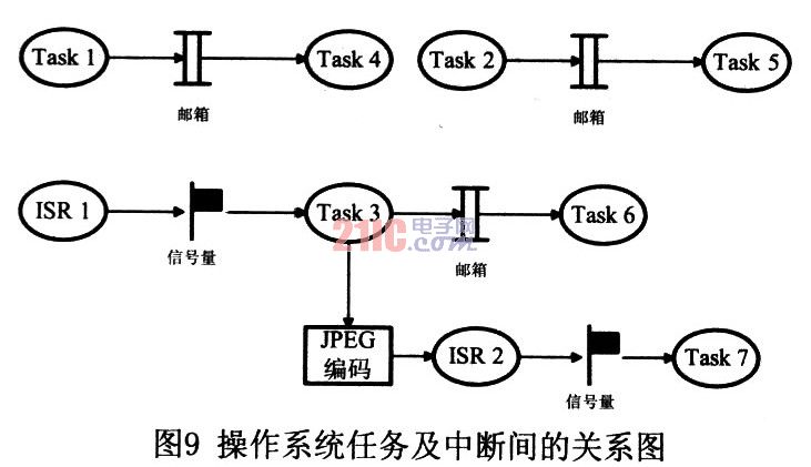
Taskl: X/Y direction acceleration and inclination signal acquisition calculation and judgment;
Task2: Acquisition calculation and judgment of vibration energy signal:
Fask3: collection of moving target detection results;
Task4: X/Y direction acceleration, tilt angle prompt SMS sending:
Task5: vibration energy prompts SMS sending;
Task6: Sending a short message of the moving target detection result;
Task7: JPG MMS sending:
ISR1: The Nios II Core2 is sent to detect the moving target message;
ISR2: JPEG encoding completed:
4 Conclusion This program collects signals through the vehicle sensor acquisition board to calculate the X/Y direction acceleration, inclination, and vibration energy. When the set threshold is exceeded, the information is sent to the client through the GPRS wireless module. The CMOS camera D5M completes the acquisition of video images, performs Sobel operator edge detection image preprocessing, and monitors the real-time output through VGA. The moving target detection is performed on the signals of two consecutive frames. When the moving foreign object is detected, the user is prompted by the short message, and the photo at the same time is taken, the JPEG image is compressed, and the GPRS MMS is sent to the client. Its design features strong real-time performance, low false alarm rate, fast transmission speed, good stability, etc., and has good practicability.
Bull nose is a common connecting way of Conveyor Belt, which is named for its shape.
The joint mesh is made of Kevlar coated with Teflon dispersion, whose technical is similar to PTFE open Mesh Conveyor Belt.
Compared to PTFE fabric conveyor belt, bull nose is much more suitable for open mesh conveyor belt, and easy to install and to repairing. In addition, the price is more competitive than alligator joint. Besides, the conveyor belt with bull nose can apply in micro wave situation.

PTFE Conveyor Belts With Bullnose
Industrial Conveyor Belts,Conveyor Belt With Bullnose,Mesh Conveyor Belt With Bullnose,PTFE Conveyor Belts With Bullnose
TAIZHOU YAXING PLASTIC INDUSTRY CO., LTD , http://www.yaxingptfe.com