
The full bridge structure has a wide range of functions in circuit design. This paper describes an isolated power supply design based on full-bridge DC-DC. The half-bridge IGBT board mentioned in the article is two sets of isolated positive and negative voltage outputs, in order to be able to become the driving and protection of the IGBT. And in the practice design, the power supply of the drive board needs to be determined according to the selected IGBT switch tube parameters and operating frequency. Then the design of the DC-DC power supply with the full-bridge control of the primary side is introduced, and the selection method of the transformer is given.
1. IGBT half-bridge integrated driver board power supply features
The effective driving and reliable protection of the half-bridge IGBT are realized by the half-bridge IGBT integrated driver board. The half-bridge IGBT integrated driver board must have two DC-DC isolated power supplies. This power supply requires a small PCB area, compact size, high reliability, and the two sub-sides of the power supply are completely isolated. In the project of high-power half-bridge IGBT integrated drive unit, a high-efficiency and reliable isolated power supply is needed for the drive unit, and a primary side control topology of the power supply transformer is designed, that is, the two sets of isolated power supply transformers share a set of full-bridge control. The idea is to increase the power density and efficiency of the power supply and save the number of power switches. The full-bridge switch tube is cleverly matched, eliminating the need for an isolated drive, reducing the PCB area on the integrated driver board.
The reason why the half-bridge IGBT integrated driver board exhibits the same load characteristics on the two-way driving is because the performance parameters of the two unit IGBTs in the upper and lower half bridges are the same, and the same-body package is adopted. Therefore, in the power supply design of the IGBT half-bridge integrated driver board, the two sets of isolated DC-DC power supply primary sides can completely share a set of control circuits. The IGBT half-bridge integrated driver board is usually embedded in the IGBT power module. It has two requirements for the driver board: The first is that the half-bridge integrated driver board has high requirements on PCB area and volume, and it is required to reduce the PCB area and volume as much as possible. Second, because the power required to drive the IGBT is large, the power density and efficiency requirements of the on-board power supply are also high.
2. Original-side shared full-bridge controlled DC-DC power supply design
This design uses two transformers to share the primary side, that is, the full-bridge circuit control DC-DC power transformer. In the normal mode, two full-bridge conversion topologies require two sets of full-bridge switches, and the pulse drive circuit of the full-bridge switch also has two sets of eight PWM pulses. The use of a shared full-bridge topology saves control circuitry and full-bridge switching, simplifying DC-DC isolated power circuits. Since the power supply is for the half-bridge IGBT drive circuit, the load is stable and can be calculated. Therefore, the full-bridge DC-DC power supply adopts open-loop control to meet the maximum power requirement. The circuit principle is shown in Figure 1. The power supply consists of four parts: a 4-channel PWM pulse generation circuit, a full-bridge drive switch, a power transformer, and a secondary-side rectification filter circuit. The DC-DC power supply input is a single +15 V power supply, the output is two sets of isolated +15 V and -10 V dual power supplies, and the negative power supply is used to reliably turn off the IGBT.
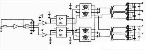
Figure 1 DC-DC schematic diagram of the primary side shared full bridge circuit
The two sets of DC-DC isolated power supplies sharing the full bridge switch work as follows: the diagonal switch tubes are turned on at the same time, and the other set of diagonals are turned off. At this time, the two core cores are simultaneously positively anti-phase-excited and the secondary side is coupled. Then, after full-wave rectification and filtering, a stable power supply is obtained. The design of the full-bridge switch operates at 360 kHz and uses full-wave rectification. Therefore, the secondary side does not require large filtering and energy storage components, which is conducive to miniaturization of the DC-DC power supply.
The full-bridge DC-DC power supply parameters are: input +15 V, output +15 V, -10 V, output power 6 W, operating frequency 360 kHz. Dynamic characteristics under rated load are required to meet: +15 V fluctuation "+1 V, -10 V fluctuation "-2V, working frequency meets 5% deviation tolerance. The operating frequency is determined by the Schmitt trigger CD40106 parameters and RC values. The specific parameters are: R=2.2kΩ, C=748 pF, VDD=15 V, VT+=8.8 V, VT-=5.8 V. According to formula (1), the oscillation frequency is calculated to be 748.792 kHz. Because the multi-vibrator output is designed to charge and discharge the two RCs, the capacity of the charging capacitor is doubled. Therefore, the oscillation frequency is 1/2 of the above calculated frequency, ie 374.396. kHz.

3. The original side shares the full bridge control of 4 PWM signals generated
The traditional full-bridge DC-DC topology consists of four identical switching tubes. It requires two reciprocal PWM control signals. Each PWM signal drives two diagonal switching transistors. The two PWM signals require dead zones to avoid Full bridge straight through. The upper arm drive of the full-bridge topology must be isolated, otherwise the correct drive cannot be completed. The isolation circuit is usually realized by optocoupler or magnetic device, and the circuit is complex and bulky. The design uses two power transformers. The primary windings share a full-bridge switch. Since the system is a single-supply input of +15 V, the full-bridge switch is implemented with two S14532ADYs with PMOS and NMOS. At this time, the PWM drive pulse does not need to be isolated. It is not necessary to isolate the upper and lower arm drive pulses of the full bridge, and use the logic gate of the oscillation circuit to drive, simplifying the control circuit, and the full bridge switch is a small-sized SO-8 package, achieving a minimum PCB design. According to this principle, the design of the full-bridge switch requires four PWM pulse drives, which are divided into two groups. Each group is reciprocally driven to drive diagonal PMOS and NMOS switches. There are dead zones between the two groups, and the specific four channels. G11, G2, G22, and G1 are 4-channel PWM drivers. T1 and T11 are two DC-DC power transformers. Only the primary windings are shown here. C is a DC-blocking capacitor, which can effectively prevent transformer core saturation. It can be seen that the diagonal switches are turned on at the same time, and the two sets of diagonal switches are alternately switched. The two transformer cores work in the I and III working quadrants, and the two-way excitation is beneficial to achieve high power density.
The general PWM drive generation method is generated by an MCU, a DSP, or a dedicated IC, and it is difficult to achieve a low cost and compact design. In this paper, the general-purpose multivibrator circuit is improved, and two diodes, resistors and capacitors are added respectively to output four PWM drive signals that meet the above requirements, which simplifies the power supply design and improves the reliability.
4. Selection and design of DC-DC power transformer
The system power supply is driven by a full bridge. The magnetic core works in the I and III quadrants. The drive must be able to prevent the core from being saturated. At the same time, it requires high efficiency and small size. Based on the above considerations, the toroidal core T10 & TImes; 6 & TImes; 5, the material is PC40, the toroidal core has small magnetic leakage and high efficiency. The specific parameters are: μi=2 400, Ae=9.8 mm2, Aw=28.2 mm2, J=2A/mm2. The system operating states are: ηB=90%, Km=0.1, fs=366 kHz, Bm=2 000 GS, according to P0=Ae&TImes; Aw&TImes; 2×fs×Bm×J×ηB×Km×10-6. It is concluded that P0=9.8×10-2×28.2 x 10-2×2×366×103×2 000 x 2×0.9×0.1×10-6=7.3 W, theoretical calculations show that the selected core meets the designed power Claim.
The transformer turns design is calculated according to equations (2) and (3), where μi is the minimum input voltage, ΔVce is the full bridge loop switch voltage drop at rated current, Dmax=0.48; μo is the output voltage rating, ΔVd is the full-wave rectifier diode voltage drop at the output rated current. The theoretical calculation of the number of primary and secondary sides is: primary side Np = 4.6 åŒ, secondary side Ns1 = 5.8 åŒ, Ns2 = 3.9 åŒ.
Np=[(μi-ΔVce)×Dmax]/(2ΔB×Ae×fs) (2)
Np=[(μo-ΔVd)×(1-Dmax)]/(2ΔB×Ae×fs) (3)
The actual debugging results are: primary side p=6åŒ, secondary side Ns1=8åŒ, Ns2=5åŒ.
5. 4-channel complementary PWM signal simulation with dead zone
The two-way DC-DC power supply transformer shares the full-bridge topology. The four-way PWM signal of the full-bridge circuit is generated by adding several passive components to the multi-vibrator circuit, and the two sets of driving signals are generated. The dead zone can effectively prevent the full bridge switching device from passing through. The working principle of the circuit is to improve the output of the general-purpose multivibrator so that the charge and discharge capacitances are different, and the waveforms with two different charge and discharge curves are generated. This difference will cause a dead zone between the two sets of PWM waves. Then, through the phase inverter and the inverter respectively, four PWM pulses satisfying the driving requirements can be generated.
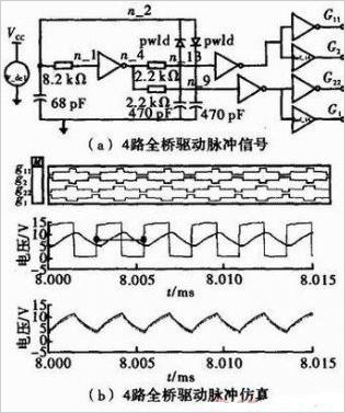
The Saber simulation schematic and simulation results of the 4-way PWM generation circuit are shown in Figure 3(a) and Figure 3(b). It can be seen from the simulation results that the four PWM pulses can meet the control requirements of the shared full bridge topology.
6. Experimental results
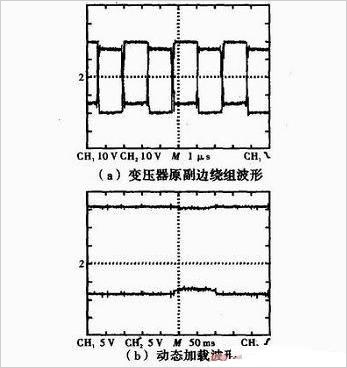
Figure 4 (a) shows the carrier side of the primary and secondary windings of the actual full-bridge DC-DC power supply transformer, where CH1 is the voltage across the primary winding and CH2 is the positive voltage of the secondary winding. Due to device dispersion, the actual test DC-DC power supply operates at 366 kHz with a frequency deviation of 3.8%, meeting design requirements. Figure 4(b) shows the dynamic loading output waveform, where CH1 is the output positive voltage and CH2 is the output negative voltage. The load during the test is 35 Ω/10 W. It can be seen that the output positive voltage is relatively stable when the sudden load is discharged, and the fluctuation is “1 V, which meets the design requirements. The negative voltage fluctuates slightly. Considering that the IGBT negative voltage is used to maintain the off state, the negative voltage is -5 ~ -15 V, so it meets the requirements of the half-bridge integrated drive power supply.
Through the analysis and calculation of the principle, this article introduces a relatively stable and high performance DC-DC isolated power supply design, which is not only easy to install, but also perfectly integrated with IGBT modules. Finally, through the analysis of the experimental results, the high efficiency and reliability of the power supply are proved, and the design goal is achieved.
3D printing on the pen machine is mainly used in 3 d printing pen, is made from a special custom Dc Gear Motor, mainly used in 3 d printing pen, pen 3 d printing machine has been updated three generations according to the requirements of product.
3D Printing Motor product introduction:
The 3D Printing Motor is based on the deceleration Motor, coupled with supporting gears and ball bearings.The role of the gear reducer is to provide lower speed and greater torque.At the same time, gear box different deceleration ratio can provide different speed and torque.It's mostly rolling.


Features: 3D Printing Motor, small size, large torque, low noise, durable, low energy consumption, customized power design, convenient installation and maintenance;
Simplify design and save space.
Features: usually used financial equipment, office equipment, electronic locks, wireless charger, remote control toys, precision instruments and meters, automobile industry, medical equipment, consumer electronics, household appliances, electric glass doors and Windows, etc., wide application range
Method of use: the best stable in horizontal plane, installed on the 3D Printing Motor output shaft parts, cannot use a hammer to knock, knock prone to press into the 3D Printing Motor drive, may cause damage to internal components, and cannot be used in the case of blocked.


Operating temperature range:
3D Printing Motor should be used at a temperature of -10~60℃.
The figures stated in the catalog specifications are based on use at ordinary room temperature catalog specifications re based on use at ordinary room temperature (approximately20~25℃.
If a 3D Printing Motor is used outside the prescribed temperature range,the grease on the gearhead area will become unable to function normally and the motor will become unable to start.Depending on the temperature conditions ,it may be possible to deal with them by changing the grease of the motor's parts.Please feel free to consult with us about this.
Storage temperature range:
3D Printing Motor should be stored ta a temperature of -15~65℃.
In case of storage outside this range,the grease on the gearhead area will become unable to function normally and the motor will become unable to start.
Service life:
The longevity of 3D Printing Motor is greatly affected by the load conditions , the mode of operation,the environment of use ,etc.Therefore,it is necessary to check the conditions under which the product will actually be used .The following conditions will have a negative effect on longevity.Please consult with us should any of them apply.â—Use with a load that exceeds the rated torque
â—Frequent starting
â—Momentary reversals of turning direction
â—Impact loads
â—Long-term continuous operation
â—Forced turning using the output shaft
â—Use in which the permitted overhang load or the permitted thrust load is exceeded
â—A pulse drive ,e.g.,a short break,counter electromotive force,PWM control
â—Use of a voltage that is nonstandard as regards the rated voltage
â—Use outside the prescribed temperature or relative-humidity range,or in a special environment.
â—Please consult with us about these or any other conditions of use that may apply,so that we can be sure that you select the most appropriate model.
when it come to volume production,we're a major player as well .each month,we rurn out 600000 units,all of which are compliant with the rohs directive.Have any questions or special needed, please contact us, we have the engineer group and best sales department to service to you Looking forward to your inquiry. Welcome to our factory.

3D Printing Motor
3D Printing Motor,3D Printing Gear Motor,3D Printing Pen Motor,3D Printing Spindle Motor
Shenzhen Shunchang Motor Co., LTD. , https://www.scgearmotor.com