At present, various consumer electronic products are constantly given new functional features, and as the complexity increases, the corresponding power consumption also increases. How to avoid excessive growth of power consumption by improving the design has become an important issue in front of hardware design engineers. Such as mobile phones, PMP, GPS and other products, the power consumed by the LCD backlight accounts for a very large proportion of the overall power consumption, and the LCD screen has a tendency to increase further, which will further increase the corresponding power. Therefore, how to reduce the power consumption of the LCD backlight has become one of the primary problems in reducing the system power consumption.
At present, the mainstream architectures of LCD screens on the market are CSTN and TFT, and they all require a backlight with a certain brightness to achieve a visible image. The brightness requirement of the backlight source is basically proportional to the size of the LCD screen, and is also related to the surrounding environment and the user's subjective experience. The domestic popular backlight scheme is that LCD screens under 2.8 inches use 2 to 4 white LEDs, and LCD screens with 2.8 to 4.3 inches use more than 5 white LEDs. Considering the LED life, indicators and price, the current of a single LED is generally controlled at 15-25mA.
Most portable devices are powered by lithium batteries. The discharge interval of the lithium battery is about 3.2 to 4.2V, and the forward voltage required for the white LED during normal operation is between 3.2 to 3.8V (IF=20mA@VF=3.5V), and when the system load suddenly increases When it is large, it will cause the battery voltage to fluctuate. Therefore, using a lithium battery to directly drive the white light LED will cause abnormal phenomena such as a dark screen or a flash screen.
The solution to this problem is to insert a primary boost drive circuit between the lithium battery and the white LED. There are currently two commonly used architectures: one is an inductive booster type, and the other is a charge pump booster type.
For the driving scheme of 5 to 6 white LEDs in portable devices, although the inductive boost architecture has more high efficiency advantages than the traditional charge pump boost architecture, the noise and the size of peripheral devices are still in this scheme. Difficult to overcome. In order to drive 5 to 6 white LEDs arranged in series, the inductive booster chip needs to output at least 16 (3.2V / LED & TImes; 5) to 21V (3.5V / LED & TImes; 6) driving voltage, and the inherent switching circuit pattern Waves are a large source of noise for other small-signal circuits. If the PWM signal is used to control the enable terminal of the boost chip for dimming operation, then not only the PWM signal itself, but the fluctuating driving voltage will also cause adverse effects on other circuits.
CAT3636 is a charge pump type capacitor boost white LED driver, especially suitable for LCD screens with 5 to 6 white LEDs as backlight. Similar to the popular capacitor boost type architecture, it does not require inductors, only a few small-capacity ceramic capacitors are needed on the periphery, and it also uses a small-sized 3mm & TImes; 3mm square TQFN-16 package. Unlike the popular capacitor boost architecture, it uses Catalyst Semiconductor's Quad-ModeTM charge pump patented technology, which can effectively improve the conversion efficiency of the backlight LED driver to reduce the power consumption of the backlight circuit.
At present, most popular charge pump LED drivers only provide three operating modes according to the ratio of output voltage to input voltage: 1 times, 1.5 times and 2 times. The Quad-ModeTM architecture adds a fourth working mode—1.33 times. The 1.33 times working mode makes the output boost voltage as small as possible, which greatly reduces the useless power consumption of the device and the associated heat loss. At the same time, the 1.33 times working mode also effectively reduces the input switch current at the battery end, which not only effectively prolongs the working time of the battery, but also minimizes the input noise of the entire system. In particular, in order to achieve 1.33 times the operating mode, CAT3636 still uses the peripheral configuration of the popular charge pump LED driver, using only two flying capacitors to achieve voltage conversion, which eliminates the need for the chip to increase the pin due to the increase in operating mode The number increases accordingly, so that the device can use a smaller but still cheap TQFN package, which is conducive to actual production and procurement.
Quad-Mode charge pump principle
CAT3636 uses the QUAD-MODETM charge pump boost architecture. The principle is different from the inductive booster circuit, the output voltage and the input voltage have a discrete multiple relationship. This charge pump has four operating modes: 1x, 1.33x, 1.5x and 2x.
The working principle of QUAD-MODETM charge pump 2 times mode is shown in Figure 1. In the first phase, the input power VIN charges two external capacitors C1 and C2. At this time, the two external capacitors are connected in parallel, the a terminal of the capacitor is connected to VIN, and the b terminal is grounded. The voltage between the two poles of the capacitor is the input voltage, that is, VC1 = VC2 = VIN. In the second phase, the external capacitor b terminal is connected to VIN, a terminal is connected to VOUT, which is VOUT = VIN + VC = 2VIN. Due to the repeated switching between the first and second phases, the charge is continuously “pumped†to the output.
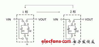
Figure 1 2x mode boost principle
Similar to the 2x mode, the working principle of the 1.5x mode is shown in Figure 2. In the first phase, C1 and C2 are connected in series between VIN and ground. The input voltage VIN charges capacitors C1 and C2, VC1 = VC2 = 1 / 2VIN. In the second phase, the two external capacitors are disconnected from ground and connected to VOUT, where VOUT = VIN + VC = VIN + 1 / 2VIN = 3 / 2VIN. Similarly, this process is repeatedly converted to achieve 1.5 times boost.
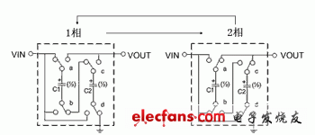
Figure 2 1.5x mode boost principle
Unlike the traditional 1.33x mode, the QUAD-MODETM charge pump uses only two external capacitors to achieve 1.33x mode. In the first phase, VIN charges external capacitors C1 and C2, and C1 and C2 are connected in series. In the second phase, capacitors C1 and C2 are disconnected from the input power supply VIN, and C1 is reversely connected to VIN and VOUT. At this time C2 remains floating. In the third phase, C1 and C2 are connected in series to VIN, and the positive electrode of C2 is connected to VOUT. The steady-state output voltage can be solved according to Kirchhoff's voltage law:
Phase 1: VIN = VC1 + VC2 (1)
Phase 2: VOUT = VIN + VC1 (2)
Phase 3: VOUT = VIN-VC1 + VC2 (3)
Substituting equation (2) into equation (3) gives:
VIN + VC1 = VIN-VC1 + VC2 (4)
VC2 = 2VC1 (5)
Substitute equation (5) into equation (1):
VC1 = 1 / 3VIN (6)
Substituting (6) into (2) gives:
VOUT = 4 / 3VIN.
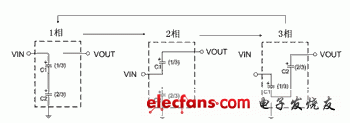
Figure 3 Catalyst's innovative 1.33x mode architecture
If the input voltage VIN is greater than the LED's forward voltage drop VF, the LED does not need to be boosted, and the QUAD-MODETM charge pump works in 1x mode.
According to the principle of conservation of energy, the input power PI of CAT3636 is equal to the power PL consumed by the external LED plus the power PE consumed by itself, ie PI = PL + PE. CAT3636's own power consumption mainly includes charge pump voltage conversion power consumption PC, internal constant current source passive power consumption PS, internal logic function module power consumption PF, and heat loss PT, that is PE = PC + PS + PF + PT. As shown in Figure 4.
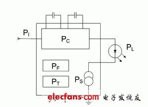
Figure 4 Power consumption distribution diagram
The conversion efficiency of CAT3636 η = PL / PI = PL / (PC + PL + PS + PF + PT). Since the PF and PT values ​​are relatively small, η≈PL / (PC + PL + PS). Under constant current operating conditions, the power consumption PL of the LED is approximately constant, which shows that in the same boost mode, as the input voltage decreases, the output voltage decreases, and the voltage acting on the internal constant current source also follows Decreases, so the power consumption PS of the constant current source also decreases, and the conversion efficiency η of the CAT3636 increases; at the same input voltage, the higher the mode, the higher the output voltage, the more power the internal constant current source consumes Larger, the conversion efficiency is reduced accordingly. This is why the LED driver with 1.33x mode has higher overall conversion efficiency than the driver with only 1.5x or 2x mode. Fig. 5 is the conversion efficiency chart of CAT3636 working in the range of lithium discharge.
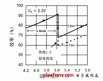
Figure 5 CAT3636 conversion efficiency
About Silicone Pencil Case:
Hey,here is a Silicone Pencil Case wanna recommend you,it's made of silicone,and it won't harm our body.Compare with traditional pencil case,our silicone pencil case is washable,durable and do not break easily.If you are interested in our silicone pencil case,welcome to visit our other pencil case such as: Cute Pencil Case ,Pencil Case Pen Bag, Pen Pencil Case ,Pencil Case Kawaii,Silicone Pencil Case,Pencil Case Holder.
Product introduction:
1.Product name:Cute Pencil Case,Pencil Case Pen Bag,Pen Pencil Case,Pencil Case Kawaii,Silicone Pencil Case,Pencil Case Holder
2.Place of origin:Guangdong China
3.Color:any pantone color
4.Effect:Any effect according to customer's requirement
5.MOQ:500pcs.
6.Package:1 pcs/opp,customized design is available.
7.Design:Customized/stock
8.Certification:FDA,LFGB,SGS,ROHS,etc.
9.Usage:Use for pencil,pen and other stationery
10.Silicone Pencil Case photos for reference.

Silicone Pencil Case
Cute Pencil Case,Pencil Case Pen Bag,Pen Pencil Case,Pencil Case Kawaii,Silicone Pencil Case,Pencil Case Holder
OK Silicone Gift Co., Ltd. , https://www.oemsiliconegift.com
