
0 Preface
In a modern society where work and life are fast-paced, old people, children or pets are lost; stolen mobile phones, luggage and other valuables; things such as keys and wallets are forgotten almost every day. Electronic anti-lost anti-theft devices are security products, which can reduce the loss and inconvenience caused to people by forgetting or missing items. Based on the application status and development requirements of electronic anti-lost anti-theft devices, this article uses RFID technology to design an electronic anti-lost anti-theft device with a color LCD touch screen, which provides a better application for the Internet of Things technology and the development of security products Application.
With the help of functions such as DPL and ACK PAYLOAD of the nRF24L01 chip, combined with the touch screen design method, this article designed an electronic anti-lost anti-theft device based on nRF24L01, ATmega48PA and TFT graphic LCD, which can be effective for the guarded elderly, children or protected items The role of anti-lost, anti-theft and anti-forgetting. Adopt high-performance controller to realize the independent control of color LCD touch screen display, wireless remote control and MCU system. The system has a high level of humanized service and strong practicability. It has good technology promotion and market application prospects.
1 System scheme design
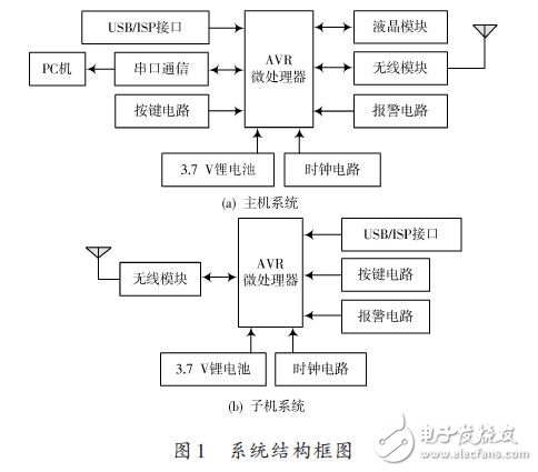
The system structure is shown in Figure 1. The electronic anti-lost anti-theft device is composed of a main unit and a sub-machine. The main unit is placed at the main controller, and the sub-machine is placed on the protected objects such as the elderly, children or mobile phones. The electronic anti-lost anti-theft device is embedded with a microprocessor in both the main unit and the sub unit. During normal operation, the sub unit emits a stable radio wave, and the host does not alarm after receiving the radio wave. When the distance between the main unit and the sub unit exceeds the predetermined distance, the main unit cannot receive the radio signal of the sub unit, and immediately sound the siren alarm (sound pressure ≤75 dB), accompanied by vibration, to attract the user's attention. If you press the search key of the host to start the search mode, the wearer of the host can find the protected object through the prompt information of the LCD touch screen and the gradual or gradual change of the alarm sound. Under normal circumstances, the lithium battery is connected to a power adapter or a computer with a USB interface to charge.
2 Hardware design
2.1 AVR microprocessor control circuit
Use ATmega48PA of ATMEL company as the microprocessor of the main control unit. The chip is a high-performance, low-power 8-bit microprocessor. The operating voltage is only 1.8 ~ 5.5 V, the operating frequency is 0 ~ 20 MHz, and it has Programmable FLASH in the system of KB. As shown in Fig. 2, the peripheral circuit of ATmega48PA includes power supply circuit, 8M clock circuit, reset circuit and USB / ISP download interface.
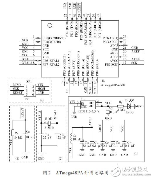
The power circuit is shown in area 1 of Figure 2. A lithium battery with a nominal value of 3.7 V is connected to the input of the integrated three-terminal voltage regulator chip REG1117-3.3 V. REG1117-3.3 V stably outputs 3.3 V DC voltage and supplies it to the system power module.
The clock circuit is shown in area 2 of Figure 2. ATmega48PA has a built-in RC oscillating circuit that can generate oscillation frequencies of 1 MHz, 2 MHz, 4 MHz, and 8 MHz. When the system requires a more accurate baud rate, it needs to be implemented by an external circuit.
The reset circuit is shown in area 3 of Figure 2. ATmega48PA has a built-in power-on reset. The fuse bit can control the reset time. Therefore, when the external reset circuit is powered on, it can directly pull a 10 kΩ resistor R3 to VCC. The 10 μF capacitor C11 is used to eliminate interference and clutter.
The ISP download interface is shown as area â‘£ in Figure 2, using a double row 2 & TImes; 5 socket to access the interface. Since there are no external components, PB3 (MOSI), PB4 (MISO), PB5 (SCK), and RESET pin are not disturbed by the ISP download interface, and can still be used normally.
Led Solar Flash Lamp,Led Traffic Signal Lights,Led Traffic Light Diodes,Led Traffic Light Countdown Timer
Jiangsu Bosiwei Optoelectronics Group Co.,ltd , https://www.bswledled.com