
0 Preface
Because of its strong anti-interference and anti-interception capabilities, burst spread spectrum communication technology has become a hotspot in military research in recent years. Its essence is to spread and despread the transmitted and received signals separately on the basis of the burst communication technology to further increase the confidentiality of the signals. A typical burst signal structure before spreading is a pilot sequence plus a piece of user data carrying information.
In order to realize the correct demodulation of a frame of burst signal, after despreading the symbol data, the carrier synchronization should be completed through a limited number of adjustments within the specified pilot sequence length, otherwise it will cause the loss of subsequent user data, resulting in demodulation failure. FLL (Frequency Locked Loop) + PLL (Phase Locked Loop) is a commonly used carrier synchronization algorithm that can correct large frequency offsets, but it is often used in continuous communication systems that do not require high synchronization time. In a burst communication system, the simulation found that the required loop adjustment times are greater than the length of the pilot sequence, and the convergence speed is not fast enough to meet the index. Therefore, some improvements were made to the algorithm by using part of the pilot sequence for FFT Calibrate the frequency, quickly reduce the frequency offset, then use FLL to reduce the frequency offset to within 10 Hz, and finally use the PLL to accurately lock.
1 Fast synchronization algorithm design
The design of a frame transmission signal at the transmitter is 168 b all 0 pilot sequence + 132 b user data, a total of 300 b, as shown in Figure 1.

After bipolar transformation, the pilot sequence becomes 168 b all 1 data, and the user data becomes data consisting of 1, -1, which is convolutionally encoded into I and Q signals, and each is differentially encoded with a different 1 023-bit I, Q two-way Gold code spreading, and then modulate the cosine and sine carriers separately in QPSK mode, the two data are combined and transmitted. At the receiving end, the corresponding signal acquisition algorithm can be used to obtain the initial phase of the Gold code of the signal and a Doppler frequency offset search value with poor accuracy. The result of this step is that the signal can be despread, but the signal still has (- 5, 5) Frequency difference of kHz, and this process consumes 40 bits of pilot symbols. In other words, within the remaining 128 b pilot length, a corresponding algorithm must be adopted to eliminate the 5 kHz frequency difference and complete carrier synchronization.
The method used in the actual receiver scheme is to use the I-channel Gold code, referred to as Gold_I, to despread the in-phase (I-channel) and quadrature (Q-channel) data, respectively, and use the obtained two-way symbol data with frequency offset to Adjust the frequency offset, and the Q way (Gold code, referred to as Gold_Q does not participate in frequency adjustment, but directly despreads the Q way data. When the frequency offset is eliminated, the I and Q ways are obtained by differential decoding, convolutional decoding and a After a series of operations, the original data can be obtained.
After the mathematical model is deduced, after the chips are aligned, the two channels of data used to correct the frequency offset after despreading the I channel and the Q channel by Gold_I are:
![]()
In the formula: C1, C2, φ1, φ2 are the constants related to the sampling rate, the position of the starting point of the despread data, and the length of the spreading code; △ f is the remaining frequency difference after frequency sweep and signal acquisition, where Δf takes the value The range is (-5, 5) kHz; Tb = 1 / Rb is the symbol period before spreading, Rb is the symbol rate, Rb = 10 Kb / s in this system; p is the signal that is despread in sequence after signal acquisition The sequence number of the symbol data of frequency offset.
The entire fast carrier synchronization algorithm process is as follows: FFT frequency correction is performed first, then FLL reduces the frequency difference, and finally the PLL is accurately locked, and the frequency offset is eliminated in three steps.
1.1 FFT frequency correction
In the algorithm, the first 16 points of I (k + p) are stored in the register, and then do FFT, then these 16 points are equivalent to sampling on a cosine wave of a known frequency at equal intervals, and the sampling period fs = 1 / Tb = Rb = 10 Kb / s, according to FFT theory, in the first 9 frequency points, set the maximum point of the obtained spectrum energy as the kth point, then the corresponding frequency ï¼¾ f = fs / N & TImes; (k-1) It is the estimated frequency, and its resolution is 10K / 16 = 625 Hz. By setting the variable u5 = I (k) Q (k-1) -I (k-1) Q (k) = C3sin (2Ï€ â–³ f / 10K) (C3 is a constant greater than 0), to determine the positive and negative of the estimated frequency, when u5 "0, -5 kHz" â–³ f "0; when u5" 0, 0 "â–³ f" 5 kHz .
1.2 FLL (frequency locked loop)
FLL usually uses an automatic frequency tracking loop (AFC) to achieve carrier frequency tracking. The structure of the AFC loop is shown in the literature.
The dot product Dot (k) and cross product Cross (k) of the two orthogonal signals obtained by despreading are:
Dot (k) = I (k-1) I (k) + Q (k-1) Q (k) (3)
Cross (k) = I (k-1) Q (k) -I (k) Q (k-1) (4)
The commonly used CPAFC method for eliminating sign ambiguity has an error function of Ud (k) = Cross (k) & TImes; sign (Dot (k)), and its frequency discrimination characteristic is nonlinear, and the frequency discrimination range is (-Rb / 4, Rb / 4), to improve it, there is the following relationship between dot product and cross product:
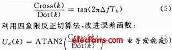
This solves the nonlinear problem of frequency discrimination of CPAFC, and doubles the frequency discrimination range to (-Rb / 2, Rb / 2).
1.3 PLL (Phase Locked Loop)
Costas loop is a commonly used phase-locked loop. It is insensitive to carrier modulation data and is widely used in radio receivers. The Costas loop phase detection algorithm used in this scheme is:
θk = sign (I (k) & TImes; Q (k)) (7)
The digital loop filter uses a second-order loop, because if its DC gain is infinite and the frequency offset is constant, the second-order loop can achieve steady-state phase error and frequency error. Its structure is shown in Figure 1.
In Figure 1, Ud is the input frequency discrimination or phase discrimination error function; C1 and C2 are loop adjustment parameters, which need to be repeatedly adjusted to the best loop performance in practical applications; Uc is the output frequency or phase control word to control the NCO Adjust the frequency or phase.
2 Algorithm simulation results
System simulation conditions are assumed as follows: input IF signal, symbol rate is 10 Kb / s, spread with 2 different 1,023-bit Gold codes, the chip rate after spreading is 10.23 Mb / s, and the sampling rate is 8 times The chip rate, the remaining Doppler frequency after scanning and signal acquisition is 4 600 Hz, and the system input signal-to-noise ratio is -16dB.
The FLL frequency tracking curve is shown in Figure 2.

1.High connection efficiency. 2. Signal processing function. 3. All kinds of functions. 4. A variety of channel selection, LED display. 5. cooperate with prefabricated cable connection.
The Relay Module integrates and serializes the single small power library relay in the electrical control cabinet, reduces the intermediate wiring link and improves the product performance. The product conforms to the development trend of miniaturization and integration, and is the renewal product of the original single relay. The installation form adopts the general 35mm U-shaped guide rail for installation, which is convenient and fast.Our products are made of Idec, Omron, Tyco, Panasonic relay and deca terminal.
Relay Module
Relay Module,Channel Relay Module,Relay Interface Module,Solid State Relay Module
Suzhou WeBest Electronics Technology Co.Ltd , https://www.webestet.com