
I discussed the basic structure of 4-wire sensor transmitters and their differences from 2-wire and 3-wire sensor transmitters. In this post, I will discuss how to build a local power output isolated 4-wire sensor transmitter similar to the one shown in Figure 1. Locally-powered 4-wire sensor transmitters are common in applications where long distance wiring is required and the current consumption of the sensor is greater than 4 mA, which also makes 2-wire transmitters inapplicable in such applications. A common example is the electromagnetic flowmeter.
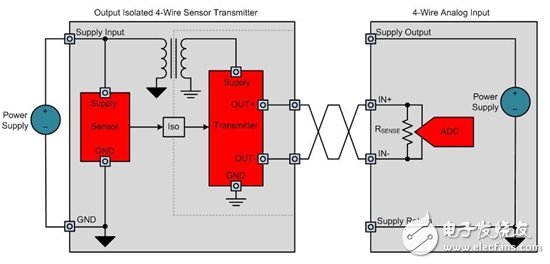
Figure 1 : Output Isolated 4- Wire Sensor Transmitter with Local Power Supply
The output stage design of a typical 4-wire transmitter is also simpler than the design of a 2-wire or 3-wire transmitter output stage because the sense resistor in the 4-wire analog input module is floating. Therefore, you can use a simple sink topology as shown in Figure 2. You can also use a source current topology, but in this case you need a 2-level design similar to a 3-wire transmitter.
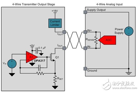
Figure 2 : 4- wire sensor transmitter output stage design
Positive output, IOUT+, is connected to a +18V supply through a current limit circuit. The negative output terminal, IOUT-, is connected to the drain of an N-type metal oxide semiconductor (NMOS) transistor. An op amp drives the gate of the NMOS transistor. According to the input voltage, VIN, the current flowing through the RSET resistor is controlled so that the VI conversion function in Equation 1 is obtained:

In an output isolated transmitter, the output stage must be completely isolated from the sensor and power supply. This requires an isolated power supply to be generated from the local power supply and a method of transmitting sensor information across the insulation barrier. As shown in Figure 3, you can use a digital isolator and a digital-to-analog converter (DAC) to achieve this goal.
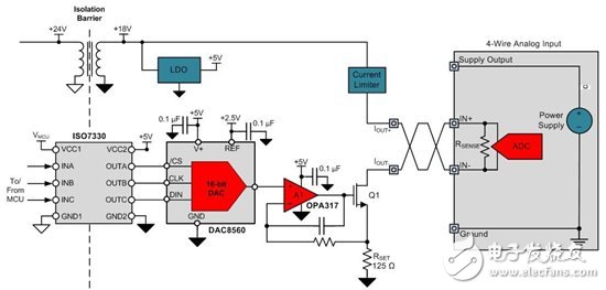
Figure 3 : Full output stage with digital isolator and DAC
The final part of the output isolated 4-wire sensor transmitter is an isolated power supply for the output stage. Depending on the input and output voltages, you can implement an isolated power supply in many ways. Figure 4 shows an example solution with an input voltage of +24V and output voltages of +18V and +5V. The LM5017 buck regulator generates an isolated +20V output from the +24V sensor supply input. The TPS7A49 low-dropout regulator (LDO) generates a +18V output, while the TPS7A1650 LDO generates a +5V output. For more information on using the LM5017 for power supply design, read this blog post from TI Power House.

Figure 4 : Isolated power supply for output isolated 4- wire transmitter
Figure 5 shows a complete output isolated 4-wire sensor transmitter with local power.
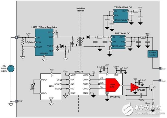
Figure 5 : Output Isolated 4- Wire Sensor Transmitter with Local Power Supply
In this blog post, I describe an example circuit design for an output isolated 4-wire sensor transmitter that consists of an isolated power solution, a digital isolator, a DAC, and an op amp circuit. In my next blog post, I will present a power-isolated and fully isolated 4-wire sensor transmitter.
Security Aluminum Alloy Die Casting
Security Aluminum Alloy Die Casting,Aluminium Alloys Die Casting,Aluminum Alloy Die Casting Mold,Aluminum Housing Aluminum Alloy Dies
Dongguan Metalwork Technology Co., LTD. , https://www.diecast-pro.com