
I. Introduction
As human society enters the era of knowledge economy, information and knowledge dissemination are realized in real time, and terminal device display technology for information exchange is developing rapidly. LCD display, which is one of display technologies, has developed rapidly, because LCD has its own The disadvantage of not emitting light, so the backlight is required in most applications. The backlights used are incandescent bulbs, cold cathode fluorescent tubes, EL sheets, and LED lamps. Each backlight technology has its own unique characteristics in a specific application environment. Among them, the advantages of LED technology are favored by people. Its advantages: long life, high efficiency, low maintenance and low power consumption; small size, allowing LCD backlight module to be thin, reducing the connection cost between LCD display and drive circuit; low voltage drive, direct drive with 5-12VDC, and conversion The time is fast, the pulse width modulation brightness is allowed, and the red, green and blue LED lights can be controlled by separate pulses, and the red, green and blue filters behind the full-color LCD display panel can be removed.
LED backlights have developed rapidly in recent years, from the early surface light-emitting mode to the side light-guided mode. The side-guide LED backlight has the advantages of low cost, low power consumption, and thin thickness compared to the bottom-emitting LED backlight. Especially with the development of LED technology, AIInGaP quaternary materials and GaN-based materials have emerged, achieving ultra-high brightness and full-color LEDs, enabling side-guided LED backlights to achieve the required number of LEDs. The requirements for illuminance and color are made possible, and satisfactory results have been achieved. The development of LED technology has promoted the rapid development of side-light LED backlights. The following describes the principles and design points of this latest development of side-guide LED backlights.
Second, the structure of the side light guide LED backlight
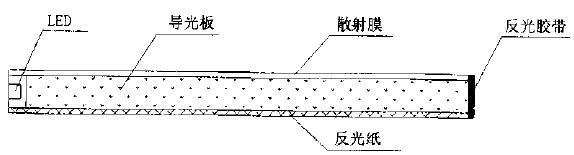
The structure of the side light guide LED backlight is shown in Figure 1. It is composed of an LED component, a light guide plate, a diffusing film, a reflective paper, an edge reflective tape, and the like.
Circle 1 side light guide LED backlight structure diagram
In the backlight assembly, the light guide is the key optical component. It is a transparent plastic polymethyl methacrylate (PMMA) material. The bottom surface is coated with white reflection points or injection molded into small bumps, and the edges are coated with white reflective material. Or cover a mirror-reflective metal tape. The scattering film is a translucent PC material that reduces brightness and improves uniformity. Reflective paper is a smooth white piece of paper that acts as a light reflection and reduces light leakage.
Third, the basic principle of side light guide LED backlight
The basic principle of the side-guided L ED backlight is to use the principle of total light reflection to efficiently transmit light and convert the line source into a surface source. Principle of total light reflection: When light is refracted from a medium with a high refractive index to a medium with a low refractive index (such as plastic to air), the refracted light is emitted at a more oblique angle than the human ray, when the angle of the person is greater than a certain angle At an angle, the light cannot be reflected in the human air and all of it is reflected inward, called total reflection or internal reflection. When the angle of refraction is equal to 90", the angle of the person is called the critical angle. The principle is shown in Figure 2.
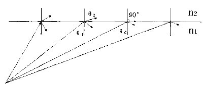
Figure 2 The principle of total anti-reflection
According to the law of light refraction and the formula n-1, Sin θ, = n2Sin θ2, the critical angle θc = Sin-1 (n 2, Sin90 ° / n2) = Sin-1 (n2 / n1) can be derived, and n2 = 1 is known. ), n1=1.491 (light guide plate plastic PMMA material), θc=Sin -10.6707=41.8°, that is, when the human light inside the light guide plate is greater than 41.8°, total reflection occurs, and the light will follow the guide. The direction of the light plate is transmitted from one side to the other side. For the light guide plate of PMMA material, the light transmittance is as high as 92%, the haze is small, and the light absorption is small, and the light can be transmitted along the plate for a long distance and the attenuation is small. . The purpose of the light guide plate is to refract light from the surface to form a bright and uniform surface light source. Therefore, the technical principle of the light guide plate is to use the principle of total light reflection to transmit light, and the other is to use it in reverse, to destroy the condition of total light reflection, to interfere with the total internal reflection optical element of light, and to change the light path of light. The light is led out from the surface of the light guide plate to form a surface light source to become a backlight. The specific design is to print a white dot on the bottom surface of the light guide plate or to inject a small bump to make the light diffusely reflect at the point. A part of the light is incident on the light guide plate at an angle smaller than the critical angle and is refracted, and a part of the light is generated. Reflected back into the light guide plate, these rays are totally reflected at the upper edge of the light guide plate and return to the point of the bottom surface. This process is repeated repeatedly until some of the light is refracted from the surface, some are absorbed by the light guide plate, and some are lost at an interface. The light refracted from the surface is visible to the human eye. This part of the light is actually the light guide plate. The backlight contributes to the brightness of the backlight detected by the instrument.
Fourth, the design of the side light guide LED backlight
The side light guide LED backlight structure design and material selection directly affect the brightness and uniformity of the backlight. In the design, both the cost factor and the brightness and uniformity of the backlight should be considered to meet the requirements of the user. The following briefly introduces the design method of the backlight for reference.
1. Design of the size and distribution of astigmatism points
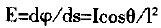
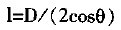
Most of the light guide plates currently used are injection molded by injection molding. The size and distribution of the astigmatism points are mainly designed by the mold manufacturer and adjusted by multiple trials to determine the mold structure. The design and calculation of the size and distribution of astigmatism points are complex and have not yet formed a complete and mature theory. According to the photometric formula:
 (1)
(1)
 (2)
(2)
 (3)
(3)
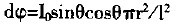
Where: E-illuminance; φ-light flux; S-receiving area; I-intensity of emitted light; θ-angle between the direction of the emitted light and the normal of the receiving surface; I-distance of the receiving surface from the LED source; Io - the normal intensity of the LED; the radius of the r-receiving area; D the thickness of the light guide plate.
According to the inverse square law of the distance of the illuminance according to formula (1), the closer to the human end, the stronger the illuminance received by the astigmatism point. As shown in Fig. 3, in addition to a direct light, the light received by the astigmatism point has multiple reflections of light, which is similarly available. The closer to the human end, the stronger the illuminance of the astigmatism point, so the astigmatism points The illuminance is different. For the sake of simple design, the astigmatism point distribution is arranged along the array of human light directions, and the astigmatism point radius is uniformly increased along the direction of human light. According to the introduction, the radius r- of the maximum point is determined according to the point spacing. The smaller the point spacing, the smaller the r- is; the larger the point spacing, the larger the rmax. The radius r- of the minimum point is calculated as follows: In an ideal state, the backlight requires uniform surface brightness, that is, the luminous flux dip of each astigmatism point reflected to the front is equal, that is, dcp=l/n., n is the astigmatism in the direction of human light. The number of points, then n = W / C, where W is the width of the light guide plate, C is the distance between the astigmatism points, and the minimum radius Rmin is calculated according to the formula (2) (3).
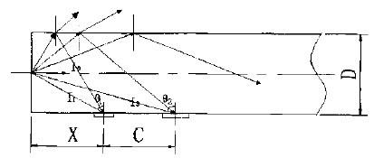
Figure 3 Schematic diagram of the relationship between the size distribution of astigmatism and light intensity
2. Design of concave incident surface of light guide plate
The population of the light guide plate is designed to be concave, which can better carry out the light pass, as shown in Figure 4. For most LED lights, the light from the surface is divergent. The concave surface allows the light to enter the light guide plate with minimal refraction, and then the curved surface at the edge of the light guide plate reflects the light into a narrow beam. In this way, more light is totally reflected back into the light guide instead of being refracted to the plastic and air interface. Thereby reducing LED light loss and improving the brightness of the backlight.
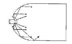
Figure 4 Schematic diagram of light reflection on a concave incident surface

Figure 5 Schematic diagram of light reflection in a curved light guide
3, the shape of the light guide plate design
For small size LED displays (less than 50mm x 100mm), flat light guides are used. For larger-size LED displays, a curved light guide plate is used. As shown in FIG. 5, the curved edge changes the angle of the total reflected light in the light guide plate, reduces the angle of the reflected light from the bottom surface, and reduces the reflection of light onto the surface of the light guide plate. The angle of the human being makes the refracted light closer to the normal direction, and on the other hand, the portion of the light that cannot be refracted from the surface of the light guide plate due to the angle of the reflected light is too large to be refracted on the surface of the light guide plate, thereby improving the LED light. Utilization, increase the brightness of the backlight.
4, choose the appropriate LED shape structure
The LED shape structure determines the distribution characteristics of the LED optical parameters. Specifically, it affects the luminous intensity of the LED. Generally speaking, the light-emitting surface is a convex LED with high luminous intensity, small half-intensity angle, and concentrated light; The surface is a flat LED with low luminous intensity, large half-intensity angle, and scattered light. For small-size LED backlights, LEDs with a flat surface should be selected to allow light to enter the light guide plate evenly. For large-size LED backlights, LEDs with a convex surface should be selected for high-brightness to ensure backlighting. The brightness of the source. At the same time, the size of the LED should be considered. The thickness of the LED is smaller than the thickness of the light guide plate, so that the light emitted by the LED enters the light guide plate as much as possible.
5, eliminate the bright line of the LED incident area
When the LED and the light guide plate are assembled on the side, a bright line along the LED direction appears after the light enters the light guide plate, which affects the brightness uniformity of the backlight. There are two ways to eliminate this: one is to use black coating or a layer of shading paper to absorb light. The other is a blank transition method, in which the bottom surface is not printed with white dots or injection small bumps. Applying the principle of total reflection, in the blank transition zone, the light is reflected back into the light guide. This blank transition zone must be determined experimentally.
6, choose the appropriate scattering film and reflective paper
The scattering film improves the uniformity, but reduces the brightness; the reflective paper improves the utilization rate of the LED light energy, reduces the leakage of light energy, and improves the brightness. Therefore, there is a high requirement for the reflectivity and transmittance of the two optical films, and should be selected. Appropriate reflectance and transmittance to achieve satisfactory results with both brightness and uniformity.
V. Conclusion
With the diversification of demand, the user has many requirements for the size, shape, illuminating color and uniformity of brightness of the side-lighting LED backlight, which puts higher requirements on the design of the material. In the actual design, the optical principle should be combined with more experiments and accumulated experience to design an excellent cost-effective backlight.
Edit: Cedar
Driverless LED Linear High Bay Light
Driverless LED Linear High Bay Light
Driverless LED Linear High Bay Light,Driverless Linear LED Bay Light,High Bay Light
Shenzhen Ri Yue Guang Hua Technology Co., Ltd. , https://www.ledlightinside.com