
Isolation requirements in transportation applications
The hybrid and electric drive systems used in cars, trucks and motorcycles have created new and unknown challenges in the transportation industry. The original 12V voltage network now needs to be supplemented by 400V or higher battery and power supply systems, which puts forward a series of new requirements for automotive OEMs and system module suppliers. All functions in hybrid / electric vehicles, such as high-voltage batteries, DC / DC converters, inverters for driving motors, and on-board charger modules connected to 230V / 380V grids, have isolation requirements.
Compared to industrial applications, automotive and transportation applications have different requirements for isolation. It is of course necessary to be solid and reliable, and it must also have strong resistance to magnetic "noise". The high power level in the car (such as a 100KW motor working at 400V, which means an operating current of 250A) will generate a strong magnetic field in the car that must be properly handled. The service life of the parts used must be long enough to meet the life expectancy requirements of the vehicle; for example, it must meet decades of use in large transportation applications. Products used in the automotive environment will drive the requirements for automotive application quality (Q1) and the operating temperature range of -40 to + 125 ° C.
At the same time, cost pressures in these areas will drive higher system integration requirements. Therefore, single-chip products with isolation functions, such as CAN transceivers, ADCs, or gate drivers, have shown advantages.
Different digital isolation technologies
In principle, there are four different digital isolation methods: optical, inductive, capacitive, and radio frequency. The first three methods are described below.
Optical isolation technology uses a transparent insulating isolation layer for optical transmission to achieve optical isolation. By driving LEDs (Light Emitting Diodes), digital signals are converted from electricity to light. Then transmit this optical signal through the isolation layer, and then use optical detection components (photodiode, phototransistor) to convert the optical signal back to electrical signal.
The main advantages of optical isolation are that light is immune to electric or magnetic fields and has the potential to deliver static signals. On the flipside of the isolation layer, the operating frequency (transmission speed) of the optical isolator is limited by the relatively slow nature of the LED. For hybrid / electric vehicle applications, the limited lifetime of optical isolation is a major disadvantage. With the passage of time, the efficiency of LEDs will decrease, so the signal drive current needs to be increased (usually starting from 10mA), so with the passage of time, this optical isolation will eventually fail.
Inductive isolation uses changes in the magnetic field between the two coils to achieve communication across the isolation barrier (isolaTIon barrier). One advantage of the inductive isolation method is the difference between common mode and differential transmission, which means that it has good noise immunity. The disadvantage of this method is that it may come from the distortion of the magnetic field, which is very common in the motor control environment of hybrid / electric vehicle applications.
Capacitive isolation uses changes in the electric field across the isolation barrier. The advantages of the capacitive isolation method are stronger immunity to magnetic fields and a longer system life. The transmission speed of capacitive isolation and inductive isolation is similar.
However, the disadvantage of the capacitive isolation method is that there is no differential signal (ie, the signal and noise share the same channel). In addition, like the inductive isolation method, they cannot directly transmit static signals (must be encoded with frequency signals first).
Isolation products
An example of the capacitive isolation method is the Texas Instruments ISOxxxx series. Figure 2 is a simplified architecture diagram of the ISO72xx system. The ISOxxxx components are integrated in a single package, integrating two dies placed on separate lead frames, and transmitting and receiving chips. Only two bonding wires connect the two dies. The actual isolation function implemented on the receiver is based on silicon dioxide (SiO2, ie glass), with copper and doped silicon as the substrate electrode capacitors (Figure 3). The use of SiO2 can bring the advantages of high reliability and long life.
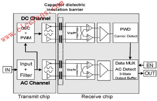
Figure: TI's ISO 72xx series architecture diagram.
Figure: TI's ISO72xx series of bare chip photos. The receiver chip on the right uses silicon dioxide isolation.
Both channels allow DC and AC communication at the same time, in addition, it also has a fault prevention function.
The basic AC channel uses an input signal and transmits it through a differential pair consisting of isolation capacitors after filtering. Then, the input end of the Schmitt trigger on the receiving chip detects it, and finally outputs the received signal through the output buffer. It can achieve very high-speed transmission, slight pulse width distortion and short transmission delay, but cannot send DC signals.
The DC channel can be used to transmit DC (or very low speed) signals through the isolation barrier. The on-chip oscillator encodes the signal into a PWM signal, which is transmitted across the isolation barrier by means of a differential signal similar to the AC channel. At the receiving chip, the signal is decoded and sent to the output buffer.
However, the DC channel is also used for fault prevention functions. For example, if the power supply voltage at the sending end is not high enough, the oscillator will stop working, which means that the receiving end will not detect the data signal, thus issuing a fault indication and outputting a high level. During normal operation (that is, with sufficient data transmission density), the output multiplexer will ignore the DC channel; but when the AC channel has no data transmission in about 4us, the DC channel will get priority. Once the AC signal has a transition, the multiplexer will immediately switch back to the channel.
A variety of isolation components are available to meet the requirements of different configurations (single to four). They can provide continuous insulation of 560V (4kV peak transient) at data rates up to 150Mbps. In addition, these components meet automotive requirements.
Reliability considerations and immunity to external electromagnetic fields
The harsh automotive and transportation environment, coupled with the long life of the vehicle and other characteristics, require components with special characteristics. Mean time to failure (MTTF) is a standard method for determining the reliability of semiconductor circuits. For isolation components, it is applicable to both integrated circuits and isolation principles. The 90% confidence level and an ambient temperature of 125 ° C should be used for evaluation. The average failure time of typical capacitor and inductor components is more than 2,000 years, while the FIT (the number of failures in 109 hours) is within 60. The average failure time of typical optical components is only 30 years, and the FIT is nearly 4,000.
In terms of immunity to magnetic fields, Figure 4 compares inductive and capacitive components. Both inductive components and capacitive components (ISO721) have high magnetic field immunity far exceeding the IEC61000 standard. However, the capacitive component ISO721 is superior, which is particularly important for harsh automotive environment applications.
Figure: Immunity to external magnetic fields.
Waterproof speaker is a kind of speaker unit which is used for devices in waterproof demanded. They have loud sound, wide frequency response range and rich bass. We can customize waterproof speakers in IP65 and IP67.
Our main Multimedia Speakers are full ranges speakers units:
1) From the diameter: we have speakers in 1" ~ 3".
2) From the power output, we have speakers of 2W ~ 15W.


FAQ
Q1. What is the MOQ?
XDEC: 2000pcs for one model.
Q2. What is the delivery lead time?
XDEC: 20 days for normal orders, 15 days for urgent orders.
Q3. What are the payment methods?
XDEC: T/T, PayPal, Western Union, Money Gram.
Q4. Can you offer samples for testing?
XDEC: Yes, we offer free samples.
Q5. How soon can you send samples?
XDEC: We can send samples in 3-5 days.
Waterproof Speaker
Waterproof Speaker ,Mini Waterproof Speaker,Portable Waterproof Speaker,Bluetooth Waterproof Speaker
Shenzhen Xuanda Electronics Co., Ltd. , https://www.xdecspeaker.com