The power demands of modern chips are closely tied to the performance and functionality required by the products they power. As integrated circuits evolve rapidly and consumer electronics—especially portable devices—become more prevalent, it's no longer feasible for designers to focus solely on speed and area optimization. Instead, power consumption has become a critical factor in system design, especially for battery-operated systems. The goal is not only to extend battery life but also to improve the overall runtime of electronic devices. Various design decisions influence power usage, from component selection to optimizing state machine configurations based on how frequently they are used.
1 Basic Concept of FPGA Power Consumption(1) Static and Dynamic Power Consumption Power consumption in FPGAs is typically divided into two main components: static and dynamic. Static power arises from leakage currents within transistors, which occur even when the device is not actively switching. These include source-to-drain and gate-to-substrate leakage. Dynamic power, on the other hand, results from the charging and discharging of capacitors during signal transitions. It depends on factors such as voltage, capacitance, and operating frequency, as shown in equation (1) [1].
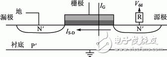
(2) Static Power Consumption Static power is primarily due to leakage current, which persists even when the chip is in a non-operational state. This leakage occurs through three main paths in a transistor, as illustrated in Figure 1. It consists of two types: source-to-drain leakage (ISD) and gate-to-substrate leakage (IG). Leakage increases as the channel length decreases and the gate oxide becomes thinner, making it a growing concern with smaller process nodes [2].

Figure 1 Composition of Static Power Consumption
Source-to-drain leakage is the dominant contributor to static power. Even when a MOS transistor is off, there is always some current flowing between the source and drain. As semiconductor technology advances and transistors shrink, this leakage increases exponentially with temperature, making it a key challenge in power management.
(3) Dynamic Power Consumption Dynamic power is caused by the switching activity of internal logic, memory, clocks, and I/Os. It is proportional to the node capacitance, operating frequency, and core voltage, as expressed in equation (1). In typical FPGA designs, dynamic power accounts for over 90% of total power consumption. Therefore, reducing dynamic power is essential for lowering overall energy use and improving efficiency.
(4) Benefits of Reducing Power Consumption 1. Lower power consumption leads to simpler and more cost-effective power supply systems, reducing the number of components and PCB size. 2. Reduced power means lower junction temperatures, minimizing the need for heat sinks or cooling fans, and preventing thermal runaway. 3. Lower temperatures enhance system reliability and reduce electromagnetic interference (EMI), especially when using fewer cooling components. 4. A 10°C reduction in operating temperature can double the lifespan of an electronic device.
Thus, minimizing power consumption in FPGAs directly improves system performance, reduces size, lowers costs, and enhances product longevity.
(5) How to Reduce FPGA Power Consumption FPGA power is mainly composed of static and dynamic components. To reduce power, both must be addressed. Static power is influenced by process technology and temperature. Semiconductor companies often adopt advanced low-power processes to minimize leakage. Additionally, managing temperature through cooling or structural design helps reduce static power.
Dynamic power in FPGAs comes from memory, internal logic, clocking, and I/Os. Several strategies can be used to reduce it:
1. Choose appropriate I/O standards. Lower drive strength or voltage levels can significantly cut power. When high-speed I/O is necessary, setting default states appropriately can help reduce power. For example, if an I/O pin defaults to high instead of low, it can save power by avoiding unnecessary DC current through termination resistors.
2. Use clock enable logic or register control to minimize unnecessary switching. By enabling data early and controlling clock signals effectively, you can avoid unnecessary transitions that increase power consumption. Another approach is to implement "data enable" on a CPLD rather than the FPGA itself, allowing the main processor to remain in standby mode longer and saving energy.
Transmission Line Steel Tubular Tower
Our steel poles are made from quality sheet through bending,
forming, automatic welding and hot galvanization. We can reach one-run
machining length of 14m and can bend sheet of thickness up to 45mm. We
adopt advanced welding procedures, automatically weld main joints and
reach rank-II welding quality. We
have got 500kV Transmission Line Tubular Tower Quality Certificate from Power
Industry Steel Tower Qualified Inspection & Test Center from 2009
year.
Transmission Line Steel Tubular Tower, Transmission Line Tower, Steel Tubular Tower, Mono Steel Tower
JIANGSU XINJINLEI STEEL INDUSTRY CO.,LTD , https://www.steel-pole.com
