
Low voltage AC lighting systems are becoming more and more popular in the market. With the promotion of retailers and home building materials, the power system has been incorporated into specific low-voltage usage rules, and users can install it themselves without having to go through a contractor. In addition, the low-voltage AC LED system can also achieve stable circuit analysis, which helps to improve product reliability.
Low-voltage AC lighting systems are becoming more and more popular in the market, from indoor accent lighting to general track lights, and even to outdoor lighting systems. Retailers and home building materials such as IKEA and Home Depot have quickly and widely communicated these technologies to customers, allowing the power system to incorporate specific low-voltage usage rules so that users can install without having to go through a contractor.
The rise of low voltage AC LED lighting applications
All low-voltage AC lighting systems use a stand-alone mains supply that provides off-line AC conversion to a low voltage solution. Under any load, even if the circuit is open, its output will not exceed 30 volts. Value (VRMS). Second, in all cases, the circuit must have a current limit of 25 amps (A), which will determine the maximum power for low voltage AC lighting applications. The typical output voltage is 12 or 24 volts alternating current (VAC), but the maximum current value of 25 amps must be maintained, whether it is a 12 volt, 300 watt (W) system or a 24 volt 600 watt system.
For the above reasons, low-voltage AC lighting is favored in light-emitting diode (LED) lighting applications, and the technology can even be applied to 300 watts of LED lighting power, equivalent to the output of three to four street lights. This gives the designer a great deal of flexibility in design, allowing for a relatively large single component or a multi-configuration lamp design from a single power supply, or a design between the two. What is certain is that the flexible LED lighting application design will make the lighting system move forward from traditional incandescent lamps.
In a low-voltage AC system, three different lighting fixtures can be considered. First, a large/high output design is installed in only one or two individual systems; secondly, ten to twenty devices can be supported in the system small light source. Medium-sized output design; and finally, a small output design that allows for fifty to one hundred illuminators in a single system.
Large array design for high light source output applications
In the case of large array designs, the benefits of LED unique design can be immediately demonstrated in two different ranges, especially in the case of more unique large lighting sources, which can create high light source output applications through large arrays. . In general, a 100 watt LED source is used in streetlight applications (using a high voltage off-line solution), although it is not recommended to use a low voltage AC system (this will result in new rules and new settings), but Designers have the opportunity to achieve the same effect with a low-voltage AC budget, starting with a 3.5 volt forward voltage and a standard LED using 350 mA, roughly 1.2 watts or about 80 LEDs each. Based on.
In order to achieve the desired output power, LED solutions using a single driver and using multiple sets of series/parallel combinations are attractive, but the industry generally discourages this design rule because it supports individual control of each LED line. The first problem encountered is that the LED and the temperature have a feedforward relationship. When the temperature rises, the forward voltage drop must be strictly controlled to avoid more current flow and further increase the temperature of the LED. The biggest impact is that under the same current sharing of different lines, the problem of improper matching will soon occur. If the current is not arranged individually, so that it can pass through the entire line, it is likely to be the source of system failure.
Use online design tools to find suitable LED drivers
As mentioned above, there are a wide variety of drives on the market that meet your needs. National Semiconductor (NS) has several LED drivers that achieve the maximum input range required, as well as simple design features and performance. Starting from the 24VAC system, this is the most attractive special large-scale luminaire. The drivers currently mentioned are DC-DC converters, so the AC signal provided by the main power supply will be carried out. In the case of rectification, based on this situation, the input conditions to the converter must be changed to: 24VRMS = 67.88VPP and the maximum input voltage range of the driver after adjustment is 34 volts.
As far as the conditions are known, there may be a specific LED specification in the design of this stage, and all the designs discussed in this paper can be developed using the WEBEBCH LED Designer online design tool such as National Semiconductor. You can type the input voltage (34 volts DC), the LED type/value and the desired output configuration. In addition, at 350 mA and Vf = 3.5 volts, a combination of nine LEDs can be driven to a 24 VAC string that is rectified to 34 volts direct current (VDC). And through the parametric search tool in the online tool, it seems that there are many applicable input ranges, but due to the limitation of the work cycle, there is not a lot of supportable lines. In this case, only National Semiconductor's LM3401 and LM3409 LED drivers can be supported. If the number of LEDs is reduced from nine to eight, the choice of drivers will increase.
It is worth noting that when the number of LEDs in the string increases, it needs to be supported by the voltage boost. The main converter topology of most low-voltage AC applications today is the buck converter (the output voltage to the LED is compared to the input. The voltage of the converter is still low), which is the main point of view for fewer LED lines.
Understand the role of the driver role
In general, it is most cost-effective to use a single driver to drive multiple LEDs as much as possible. However, it is not advisable to use parallel lines in a single driver. Instead, it is desirable to extend the series as much as possible; the advantage is that even if the line is strictly regulated And protection also ensures that the current through the LEDs is the same. In this way, a large input voltage can easily drive a large number of LED lines, but after rectification, the line usually loses half of the AC voltage value, so its advantages are greatly reduced; to solve this problem, Change the boost solution (when the output voltage is greater than the input voltage) to reduce the burden of driving a large number of LED lines.
Another point is that if the string can maintain less than twenty LEDs (Vf = 3.5V and 350mA LED drive current), the boost output can be maintained at low voltage limits (with a low voltage limit of 84.85VPP) 70VDC), available through any National Semiconductor LM342X driver, provides overvoltage/undervoltage protection, current limiting, and optional overtemperature protection.
In addition, the understanding of the characteristics of the driver device plays an important role in the circuit design, such as whether to support pulse width modulation (PWM) dimming, analog dimming, etc., or whether to change some light source output to add some optical requirements and overheat protection The above considerations are all factors that drive.
In response to these needs, the LM3421/23 driver features the ability to block and detect additional false alarms, and is a suitable component for applications that want to achieve high-level protection and provide microcontroller (MCU) response. The LM3424's built-in thermal protection feature facilitates optical or thermal protection applications (reducing the output current associated with LED temperature); while the LM3429 is the most basic driver for this family of products, it still has a boost application. Overvoltage protection and current limiting to assist with boost detection.
Figure 1 shows a circuit diagram that drives twenty LEDs, each with an average current of 350 mA and a forward voltage of 3.5 volts. In addition, the circuit may require analog dimming (when the input is reduced, the output of the source will be Reduced) to change to meet simple and fully protected line drivers. For more stringent color accuracy, PWM dimming is available.
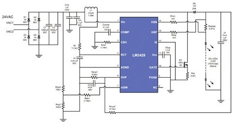
Figure 1. Large array design uses the LM3429's boost configuration, which uses a 24VAC system to drive twenty LEDs at 350mA.
Large capacitance scheme reduces chopping and prolongs electrolyte capacitor life
A simple concept is to apply a boost solution to recover the voltage lost when AC-rectified to drive a large number of LED strings, and still remain in the low-voltage limit, which is about 27 watts consumed by the front end (24.5 at 92% efficiency) Tile LED), so it is obvious how the system expands into a high-profile design with complete protection for each line under a single accessory.
If four such circuits are further used, each line can achieve a 100 watt design goal of complete protection and control. To implement this architecture, a general rectifier may be used at the front end (only bridges with a current rate of 4) are required. The tube and the X4 capacitor of C1/C2). In addition, LED lighting design has 300 to 600 watts of available power in a low voltage system, and the total current of 25 amps has many options for designers. For example, from D1 to D4, the headroom of the maximum voltage and current needs to be specified. The output capacitor can be expressed by the following equation:
C=0.7(I)/ΔE(f)
Where I represents the input current to the downstream circuit (DC to DC conversion region), ΔE is the allowable chopping voltage, and f is the AC frequency. Since this design is 92% efficient, given the LED power of 24.5 watts, this represents 26.6 watts of power in the DC-to-DC region of the front end; and after rectification (34 VDC), 26.6 watts from the 24 VAC source and produces approximately 782 watts. The average input current of the mA, so that the specifications of the diode rectifier can be properly adjusted.
Acceptable chopping, on the other hand, also affects the capacitance requirement, for example, by performing an 800 mA input current and allowing a 1 volt chop on the 120 Hz line (since the bridge rectifier is 2 x) 60Hz) requires a large capacitance of 9,300μF; if it is a 3 volt chopping, only 1,500μF is needed. Since the reduction of chopping provides better protection for the life of the electrolyte capacitor, in this case, a large capacitor will be the possible choice. .
Small array design challenges to reduce the capacitance temperature is imperative
Another extreme design range is a small array design that can be a single LED component or a single component with three components that can turn 1 watt into a 3 watt modern LED lighting efficiency solution in the environment and park Popular in lighting equipment.
Small array design for 105 °C rated capacitors, let them keep cooling at 65 ° C and lower, which is the weakest part of the design; however, because the electrolyte capacitance is lower than the rated temperature of 10 ° C, Double the service life means that if a designer can maintain a temperature of 65 ° C or better, the 105 ° C rated capacitance will be extended by 16 times the rated life, at this ratio, 5,000 hours of rated capacitance can be extended Up to 80,000 hours, for small array designs, although it is a great challenge, it is still imperative.
This proves that good thermal design plays a key role in LED applications, and the use of efficient drives such as the LM3429 makes design challenges easier to solve. In this design, the most popular device is the single junction field effect transistor (FET) M1 switch, which can achieve a temperature performance of about 65 ° C, although it does not have much impact, but the designer must determine it and other important heat sources The electrolyte capacitance is kept at a distance and the components on all the boards are kept below 50 °C. It can be seen that the heat energy radiated from the LED is always the biggest challenge, not electronics.