
Author: LED lighting technical director Hamming room
Overview
In LED product applications, it is often desirable to assemble multiple LEDs onto a circuit substrate. In addition to playing the role of the LED module structure, on the other hand, as the LED output power is getting higher and higher, the substrate must also play the role of heat dissipation to transmit the heat generated by the LED crystal, so in the material selection. Must meet structural strength and heat dissipation requirements.
Conventional LEDs do not have a large heat dissipation due to the small amount of heat generated by the LEDs. Therefore, a general copper foil printed circuit board (PCB) can be used. But with the increasing popularity of high-power LEDs, PCBs are no longer sufficient to meet cooling needs. Therefore, the printed circuit board needs to be attached to a metal plate, the so-called Metal Core PCB, to improve its heat transfer path. In addition, there is also a method of directly forming an insulating layer or a dielectric layer on the surface of the aluminum substrate, and then forming a circuit layer on the surface of the dielectric layer, so that the LED module can directly bond the wires to the circuit layer. At the same time, in order to avoid increasing the thermal impedance due to the poor thermal conductivity of the dielectric layer, a perforation method is sometimes adopted, so that the heat spreader at the bottom end of the LED module directly contacts the metal substrate, that is, the so-called chip is directly adhered. Next, several common LED substrate materials are introduced and compared.
Printed circuit board (PCB)
The commonly used FR4 printed circuit board has a thermal conductivity of 0.36 W/mK and a thermal expansion coefficient of 13 to 17 ppm/K. It can be a single layer design or a multi-layer copper foil design (Figure 2). Advantages: mature technology, low cost, and can be applied to large-sized panels. Disadvantages: Poor thermal performance, generally used in traditional low-power LEDs.
Figure 1 Heat dissipation substrate of multilayer PCB
Metal-based printed board (MCPCB)
Due to the poor thermal conductivity of the PCB and poor heat dissipation performance, it is only suitable for traditional low wattage LEDs. Therefore, the printed circuit board is then attached to a metal plate, the so-called Metal Core PCB. The metal-based circuit board is made of a metal-based copper clad laminate (also referred to as an insulating metal substrate) by a printed circuit manufacturing process.
Depending on the metal substrate used, it is divided into a copper-based copper clad laminate, an aluminum-based copper clad laminate, and an iron-based copper clad laminate. Generally, an aluminum substrate is generally used for heat dissipation of the LED . As shown below:
Figure 2 Structure of a metal-based circuit board
Advantages of MCPCB:
(1) Heat dissipation
Conventional printed board substrates such as FR4 are poor conductors of heat, insulated between layers, and heat is not emitted. Metal-based printed boards can solve this heat dissipation problem.
(2) Thermal expansion
Thermal expansion and contraction are the common nature of matter. The coefficient of thermal expansion (CTE) is different. The metallized hole wall of the printed circuit board (PCB) and the connected insulating wall have a large difference in the CTE of the Z axis, and the generated heat cannot be eliminated in time, and the thermal expansion and contraction causes the metallized hole to be cracked and broken. The metal-based printed board can effectively solve the heat dissipation problem, thereby alleviating the thermal expansion and contraction of different materials on the printed board, and improving the durability and reliability of the whole machine and the electronic equipment.
(3) dimensional stability
Metal-based printed boards are clearly much more dimensionally stable than printed boards of insulating materials. Aluminum-based printed board, aluminum sandwich board, heated from 30 ° C to 140 ~ 150 ° C, the size change is 2.5 ~ 3.0%. MCPCB structure currently available on the market standard metal-based copper clad sheet from three different materials It is composed of copper, insulating layer, metal plate (copper, aluminum, steel plate), and aluminum-based copper clad laminate is the most common.
a) metal substrate
Take the American Begs as an example, see the following table (Figure 3):
b) insulation
It acts as an insulating layer and is usually 50~200um. If it is too thick, it can act as an insulator to prevent short-circuiting with the metal base, but it will affect the heat dissipation; if it is too thin, it can dissipate heat well, but it is easy to cause short circuit between the metal core and the component leads.
The insulating layer (or prepreg) is placed on an anodized, insulated, aluminum plate and bonded together by a copper layer on the surface of the laminate.
c) copper foil
The back side of the copper foil is chemically oxidized and the surface is galvanized and plated with brass to increase the peel strength. The copper thickness is usually 0.5, 1.2 ç›…. For example, the United States Bergs company uses ED copper, copper thickness is 1, 2, 3, 4, 6 ç›… division 5 kinds. The aluminum substrate we made for the communication power supply uses a 4 inch copper foil (140 micron).
MCPCB technical parameters and characteristics
Technical parameters (Figure 4)
Features:
(1) Thin insulation layer with low thermal resistance
(2) High mechanical strength
(3) Standard size: 500 × 600mm
(4) Standard size: 0.8, 1.0, 1.2, 1.6, 2.0, 3.0 mm
(5) Copper foil thickness: 18um, 35um, 70um, 105um
MCPCB application product example (Figure 5)
Ceramic Substrate
Ceramic Substrate: Sintered ceramic material as LED package substrate, with insulation, no dielectric layer, good thermal conductivity, thermal expansion coefficient (4.9 ~ 8ppm / K), matching with LED chip, Si substrate or Sapphire, compare There is no thermal stress or thermal deformation due to heat.
A typical ceramic substrate, such as AIN, has a thermal conductivity of about 170 to 230 W/mK and a thermal expansion coefficient of 3.5 to 5 ppm/K. The price is more expensive, the size is limited to 4.5 square inches or less, can not be used for large-area panels, suitable for high-power environment high-power LED.
Comparison of thermal characteristics of AlN ceramic substrates and other materials (Fig. 7)
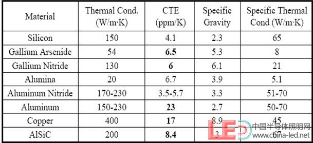
The AlN ceramic substrate has good thermal conductivity and the thermal expansion coefficient LED chip (CTE=5ppm/K) is matched.
Direct copper bonded substrate (DBC Substrate)
Features:
Directly co-fired and bonded ceramic materials on a metal substrate, which has high thermal conductivity and low thermal expansion, and also has dielectric properties.
Allow process temperature and operating temperature up to 800 °C.
The direct copper bonded substrate developed by the company Curamik in Germany is between the copper plate and the ceramic (Al2O3, AlN). O2 is first introduced to react with Cu to form CuO, and the melting point of pure copper is reduced from 1083 °C to 1065 °C. Eutectic temperature. Subsequent heating to a high temperature causes CuO to react with Al2O3 or AlN to form a compound, and the copper plate is tightly bonded to the ceramic dielectric layer. (Figure 5)
The copper substrate containing the dielectric layer has good thermal diffusion capability, and the dielectric layer such as Al2O3 has a thermal conductivity of 24 W/mK and a thermal expansion coefficient of 7.3 ppm/K. For AlN, the thermal conductivity is 170 W/ mK, thermal expansion coefficient of 5.6ppm / K, has better thermal performance than the previous substrates, and is suitable for high temperature environment and high power or high current LED.
Figure 8 Production process of direct copper bonded substrate
Comparison of characteristics of various LED substrate materials (Figure 9)
The substrate material should be selected according to the actual product application. The low-power LED does not generate much heat, and the PCB substrate can be used. For high-power LEDs, in order to meet the heat dissipation requirements, MCPCB substrate, ceramic substrate or DCB substrate is used to meet the performance requirements. The cost should be considered.
LED thermal interface material
Why use interface materials?
Figure 10 LED interface gap There are many gullies or gaps between the bottom surface of the heat sink and the surface of the LED chip , all of which are air. Since air is a poor conductor of heat, air gaps can seriously affect heat dissipation efficiency, making the performance of the heat sink greatly compromised or even ineffective. In order to reduce the gap between the chip and the heat sink and increase the contact area, it is necessary to fill with a heat conductive material having good thermal conductivity, such as a thermal conductive tape, a thermal conductive gasket, a thermal conductive silicone, a thermal conductive adhesive, a phase change material, and the like.
Liqui-Bond SA2000 thermal paste (example)
Introduction
Liqui-Bond SA2000 is a high thermal conductivity and insulating silicone adhesive produced by Shenzhen Hengtong Thermal Conductive Co., Ltd. It maintains good mechanical and chemical properties at low or high temperatures. The toughness of this material helps to reduce CTE pressure during heat transfer and at the same time cures as the product heats up.
feature:
Thermal conductivity: Thermal conductivity 2.0 W/mK
Eliminate mechanical firmware requirements
Stable mechanical and chemical properties
Maintaining the structure of the object in severe environments
application:
High-power LED and heat sink substrate bonding
Bonding components on uneven surfaces
DM6030HK-SD high thermal conductivity silver glue (example)
Introduction:
DM6030 HK-SD is a high thermal conductivity silver-doped organic adhesive produced by Shenzhen Hengtong Thermal Conductive Co., Ltd., which is specially developed for high-power LED bonding and fixed chip applications. The product has a long-term anti-volatilization and drying ability for dispensing and bonding a large number of parts (dice), and can prevent the resin from splashing out before processing.
product features:
High thermal conductivity: thermal conductivity up to 50w/mk
Low resistance: resistance as low as 10μcm
Alternative solder
Store and transport at room temperature
Good liquidity
Application:
High Power LED chip package bonding
General metal mold welding
HN-G high performance thermal grease (example)
Introduction:
HN-G thermal grease is a high thermal conductivity insulating silicone material developed by Shenzhen Born Business Co., Ltd., which is specially developed for the filling of various instruments and electronic components and assemblies. Widely applied to various electronic products, electrical equipment, heating elements (power tubes, thyristors, electric reactors, etc.) and heat sinks (heat sinks, heat sinks, housings, etc.) between the contact surface, heat transfer Media function.
Performance parameters [Figure 11]:
heat sink
effect:
The function of the heat sink is to absorb the heat transferred from the substrate or the chip, and then radiate to the external environment to ensure the temperature of the LED chip is normal. Most radiators are designed for natural convection and forced convection. Take aavid 62500 as an example.
Figure 12 aavid 62500 radiator
Performance parameters [1]:
• Thermal resistance Θ = 4.6 °C/W
• Material = Al 6063-T5 Extrusion
• Weight = 100g
• Emissivity = 0.85
• Heatsink efficiency = 98.9%
• Input heat = 5W
• Heat source = 0.57X0.57
• 5W cooling temperature = 46.9 °C
High-power LED heat sink structure
How to effectively dissipate the heat generated by LED devices into the environment is also a key. Commonly used heat sink structures are divided into passive and active heat dissipation. For high-power LED packages, active heat dissipation must be used, such as fins + fans, heat pipes, liquid forced convection, microchannel refrigeration, phase change refrigeration, and so on.
(1) In the case of low power density and low cost requirements, the fin + fan cooling method is preferred;
(2) For applications with low cost requirements, medium power density, and small package size, it is more appropriate to use heat pipes;
(3) For applications where the power density is high and the LED device temperature is low, it is more feasible to use liquid forced convection and microchannel cooling.
in conclusion
The difference between the heat generated by the LED electroluminescence process and the working environment temperature (Ta) causes a change in the junction temperature Tj of the LED chip. The LED is a temperature sensitive device, and when the temperature changes, the performance and package structure of the LED are affected. Affect the reliability of LEDs.
In the heat dissipation design, the most important issue is to effectively reduce the thermal resistance of the chip's light-emitting layer to the environment. Therefore, it is very necessary to select a suitable heat sink substrate, interface material, and heat sink.
The structure of LED lighting fixtures may vary widely and may result in a combination of different heat sinking materials, but ultimately based on the optimization of heat dissipation and light exit channels.
7 inch, 8 inch, 9.7 inch, 10 inch, 12.1 inch, 15 inch, 15.6 inch, 17 inch POS Monitor with factory own molds.
7 inch 800*600 or 1024*600
8 inch 800*600 or 1024*768
9.7 inch 1024*768
10 inch 800*600
10.1 inch widescreen 1280*800
12.1 inch 800*600 or 1024*768
12.1 inch widescreen 1280*800
15 inch 1024*768
15.6 inch widescreen 1366*768 or 1920*1080
17 inch 1280*800
Most of them are support resistive touch function.
If you need capacitive touch, we have 8-24 inch for options.
All in One Touch PCs from 10.1-32 inch.


Shenzhen Bolinia Technology Co., Ltd. is a manufacturer for 7-32 inch lcd monitors and displays over 13 years. Original factory with assembling line in Shenzhen. Product ranges from plastic monitor, Metal Monitor , resistive touch monitor, Capacitive Touch Monitor, Open Frame Monitor , Embedded Monitor to SDI broadcasting monitor. Square monitor or wide screen monitors are available with different resolutions. Members in Alibaba, Global Sources and Made-in-China. Newly launched 10.1-32 inch All in One PC and portable LCD monitors.
Plastic or metal casing monitor from 7 inch
to 24 inch.
Single Touch Monitor with resistive 4 wire and 5 wire for options from 7 inch
to 22 inch.
Multi-touch projected capacitive touch ( PCAP Touch or PCT) monitor from 8 inch
to 24 inch.
SDI monitor from 15 inch to 21.5 inch.
High Brightness Monitor from 10 inch to 22 inch.
Mirror Image Monitor with
size: 8 inch, 9.2 inch, 10.4 inch, 12.1 inch, 15 inch, 17 inch, 19 inch, 20.1
inch and 22 inch.
All In One PC with Android system with 10.1 inch, 13.3
inch, 15 inch, 15.6 inch, 18.5 inch, 21.5 inch, 23.6 inch, 24 inch, 27 inch and
31.5 inch.
Portable LCD Monitor with 12.5 inch , 13.3 inch and 15.6 inch.
Products mainly used in ATM, POS, CCTV security, Information checking, Kiosk,
BGA repairing station, Lottery terminals, microscopes and similar applications. Portable LCD monitors perfectly compatible to PS4/PS3/PS2/Xbox ONE/Xbox 360, game consoles,
PCs, Macs, Raspberry Pi, laptops, cameras and tablets.


POS Monitor
POS Monitor, POS Display, POS LCD Monitor, POS Terminal, POS LCD Screen Monitor
Shenzhen Bolinia Technology Co., Ltd. , http://www.bolinia.com