
Circuit function and advantages
This circuit shows how to use the precision analog microcontroller ADuCM360 / ADuCM361 in precision thermocouple temperature monitoring applications. ADuCM360 / ADuCM361 integrated dual channel 24-bit analog-to-digital converter (ADC), dual channel programmable current source, 12-bit digital-to-analog converter (DAC), 1.2 V internal reference voltage source, ARM Cortex-M3 core, 126 kB Flash memory, 8 kB SRAM, and various digital peripherals such as UART, timer, SPI, and I2C interface.
In this circuit, the ADuCM360 / ADuCM361 is connected to a thermocouple and a 100 platinum resistance temperature detector (RTD). RTD is used to perform cold junction compensation.
In the source code, the ADC sampling rate is 4 Hz. When the ADC input programmable gain amplifier (PGA) has a gain configuration of 32, the noise-free code resolution of the ADuCM360 / ADuCM361 is greater than 18 bits.
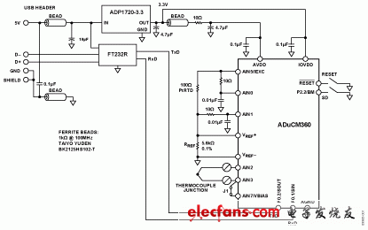
Figure 1. ADuCM360 / ADuCM361 is used as a temperature monitoring controller and thermocouple interface (schematic schematic, not all connections are shown)
Circuit description
The following features of ADuCM360 / ADuCM361 are used in this application:
-In the software, a 24-bit sigma-delta ADC with 32 times the PGA gain is configured for the thermocouple and RTD. ADC1 continuously switches between thermocouple signal sampling and RTD voltage signal sampling.
-Programmable excitation current source to drive controlled current through RTD. The dual-channel current source can be configured from 0A to 2mA. This example uses a 200A setting to minimize errors caused by RTD self-heating effects.
-The ADC in ADuCM360 / ADuCM361 has a built-in 1.2V reference voltage source. Its internal reference voltage source has high accuracy and is suitable for measuring thermocouple voltage.
-The ADC in ADuCM360 / ADuCM361 has a built-in external voltage reference voltage source. It measures RTD resistance; it uses a ratiometric setting and connects an external reference resistor (RREF) to the external VREF + and VREF pins.
-Bias voltage generator (VBIAS). VBIAS is used to set the thermocouple common-mode voltage to AVDD / 2.
-ARMCortex-M3 core. The powerful 32-bit ARM core integrates 126kB flash memory and 8kBSRAM memory to run user code, configure and control the ADC, process ADC conversion through RTD, and control communication of the UART / USB interface.
-UART is used as a communication interface with the PC host.
-Two external switches are used to force the device into flash boot mode. With SD at low level and switching the RESET button at the same time, the ADuCM360 / ADuCM361 will enter the boot mode instead of the normal user mode. In boot mode, the internal flash memory can be reprogrammed via the UART interface.
The signals generated by the thermocouple and RTD are very small, so you need to use PGA to amplify these signals.
The thermocouple used in this application is of type T (copper-constantan) with a temperature range of −200 ° C to + 350 ° C. The sensitivity is about 40V / ° C, which means that the ADC can cover the entire temperature range of the thermocouple in bipolar mode and 32 times PGA gain setting.
RTD is used to perform cold junction compensation. This circuit uses platinum 100Ω RTD, model is Enercorp PCS 1.1503.1. It uses 0805 surface mount package. The rate of temperature change is 0.385Ω / ° C.
Note that the reference resistor RREF should be a precision 5.6kΩ (± 0.1%) resistor.
The USB interface of ADuCM360 / ADuCM361 is realized by FT232R UART to USB transceiver, which directly converts the USB signal to UART.
In addition to the decoupling shown in Figure 1, the USB cable itself must also use ferrite beads to enhance EMI / RFI protection. The ferrite bead used in this circuit is Taiyo Yuden # BK2125HS102-T, and its impedance at 100 MHz is 1000Ω.
This circuit must be built on a multilayer printed circuit board (PCB) with a large area ground plane. For best performance, proper layout, grounding, and decoupling techniques should be used.
The PCB used to evaluate the circuit is shown in Figure 2.
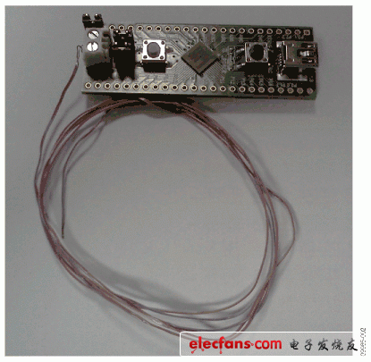
Figure 2. The EVAL-ADuCM360TCZ board used in this circuit
Three-axis Stabilizer is composed of pan axis, rolling axis and tilt-axis. With a gyro-stabilized gimbal system, it keeps stabilized or steerable horizon with automatic calibration to give you an unprecedented smooth shooting experience.
3 axis gimbal stabilizer can be divided into 4 parts, including Three-axis Smartphone Stabilizer, three axis micro dslr stabilizer, 3 axis camera stabilizer and 3axis motion camera stabilizer.

For different consumer, there are 2 kind of 3 axis gimbal stabilizer for them, which are consumer stabilizer and Professional Stabilizer.

Wewow focusing on handheld stabilizer is a technology company which does R & D independently. With Wenpod series product released, the company achieved the industry's praise and quickly became the leader of the smart stabilizer industry.
Our service
1. Reply to you within 24 hours.
2. Already sample: within 1-2days.
3. Shipping date: within 24 hours once get the payment.
4. 12 months warranty.
5. After-sales service, solve within 3 working dates.
If you have any questions, please contact with us directly.
Wewow appreciates domestic and international business relationship!
Three-Axis Stabilizer,Popular Three-Axis Mobile Phone Stabilizer,Professional Three-Axis Stabilizer,Handheld Three-Axis Gimbal Stabilizer
GUANGZHOU WEWOW ELECTRONIC CO., LTD. , https://www.stabilizers.pl