
**Introduction**
Author: Alex He (Ho Ye), Senior Applications Engineer at Xilinx.
UIO stands for Userspace I/O. In this article, UIO refers to the UIO device and its corresponding driver. Though small in the Linux kernel ecosystem, it is widely used for custom devices and their drivers. The UIO kernel driver allows user space applications to access device memory and interrupts, enabling flexible and highly customized system designs.
So how does this relate to FPGAs? Well, FPGAs are incredibly versatile in the hardware world. This combination of software and hardware is exactly what makes them powerful.
This lab project demonstrates how to implement multiple UIOs on the Zynq UltraScale+ MPSoC ZCU102 development board from Xilinx. It includes hardware design, Linux BSP development using Xilinx tools, and a test application to validate the setup.
The ZCU102 features a quad-core ARM Cortex-A53, dual-core Cortex-R5, and a Mali-400 MP2 GPU on the Processing System (PS) side. The Programmable Logic (PL) side contains the FPGA fabric. The PS handles control, while the PL accelerates specific tasks through AXI interconnect. Although this experiment may seem overkill, it's a great way to explore the capabilities of the ZCU102. If you don't have the board, you can try it on a Zybo or ZedBoard.
**Experimental Report**
Experimenter: Me
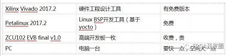
**Experimental Materials:**
**Hardware Design**
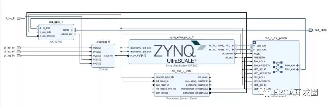
We start by creating a Vivado project tailored for the ZCU102 EVB. Using IP Integrator, we connect the PS and add five UIO inputs on the PL side. One of these is a GPIO module with interrupt output and memory mapping, while the other four are connected to DIP switches on the board. These are routed via a Concat IP block to the `ps_pl_irq` pin of the PS. For more details on the board configuration, refer to [1] UG1182 and [2] UG1085.
Next, we define the pin constraints:
```tcl
set_property PACKAGE_PIN AN13 [get_ports pl_irq_ll]
set_property IOSTANDARD LVCMOS33 [get_ports pl_irq_ll]
set_property PACKAGE_PIN AM14 [get_ports pl_irq_lh]
set_property IOSTANDARD LVCMOS33 [get_ports pl_irq_lh]
set_property PACKAGE_PIN AP14 [get_ports pl_irq_ef]
set_property IOSTANDARD LVCMOS33 [get_ports pl_irq_ef]
set_property PACKAGE_PIN AN14 [get_ports pl_irq_er]
set_property IOSTANDARD LVCMOS33 [get_ports pl_irq_er]
```
With Vivado’s rich IP library and smart connectivity, even a simple digital design can be completed quickly. The full design is shown below.
**Software Design**
For the Linux BSP, we use Xilinx Petalinux, which is based on Yocto. It simplifies the process of integrating hardware and supports out-of-tree drivers, device tree modifications, and QEMU simulation. Below is a brief command sequence:
```bash
petalinux-create -t project --template zynqMP -n zcu102-pl2ps_irq
cd zcu102-pl2ps_irq
petalinux-config --get-hw-description
petalinux-config -c kernel
# Enable UIO_PDRV_GENIRQ driver
CONFIG_UIO=y
CONFIG_UIO_PDRV_GENIRQ=y
petalinux-build -c device-tree
```
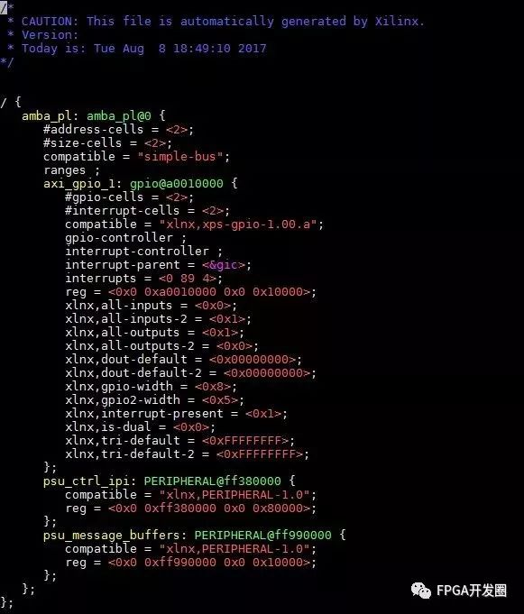
After building, the device tree file `pl.dtsi` is generated. However, since PIN-based UIOs aren’t IP blocks, we need to manually update the device tree. We modify the GPIO UIO endpoint and add entries for the DIP switches, ensuring correct interrupt numbers and trigger types.
Petalinux allows us to customize the device tree using `system-user.dtsi`, located at `./project-spec/meta-user/recipes-bsp/device-tree/files/system-user.dtsi`.
There are two ways to configure the UIO endpoints with the `uio_pdrv_genirq` driver:
1. Use `bootargs="uio_pdrv_genirq.of_id=generic-uio"` in the kernel command line.
2. Load the driver with `insmod uio_pdrv_genirq.ko of_id=generic-uio`.
After making changes, we rebuild the image and package it into `BOOT.bin` and `image.ub` for booting from an SD card.
**Test**
The `uio_pdrv_genirq` driver provides a mechanism for userspace applications to handle interrupts. Each UIO device appears as `/dev/uioX`. User-space drivers can read from these nodes, blocking until an interrupt occurs. The driver then disables the interrupt, and the application must explicitly enable it again using `write()`.
The driver source code is available at `driver/uio/uio_pdrv_genirq.c`.
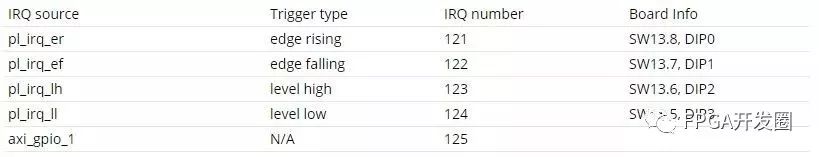
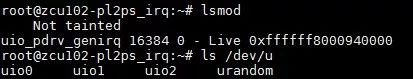
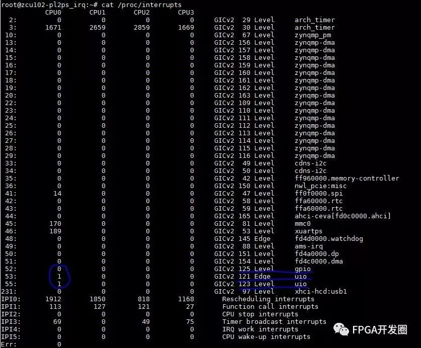
Once the kernel is booted and the driver is loaded, we check `/proc/interrupts` to verify that the UIO interrupts are registered.
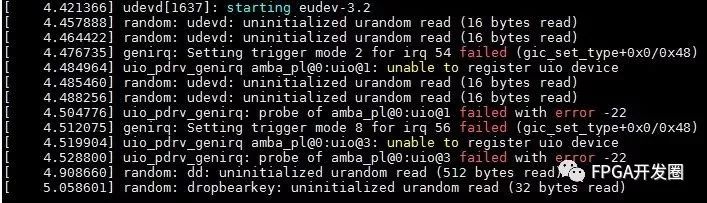
However, we noticed that two interrupts (IRQ 122 and 124) were missing. This is because the hardware does not support Edge-falling or Level-low trigger modes. The kernel logs confirm this issue.
**Test DIP UIO – Method 1**
We tested two DIP switches and observed that the interrupt always returned 1, regardless of the switch state. To resolve this, the application must call `uio_pdrv_genirq_irqcontrol()` to re-enable the interrupt. A quick workaround is to use the `echo` command:
```bash
echo 0x1 > /dev/uioX
```
This triggers multiple interrupts, allowing us to test the functionality effectively.
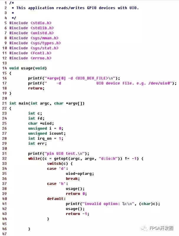
**Test DIP UIO – Method 2**
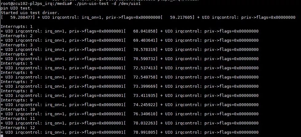
For a more advanced approach, we wrote a simple user-space application to handle the interrupts. The code is shown below.
After compiling the code using the Petalinux cross-compiler, we copied the binary to the SD card and ran the test program. We also added an `irqcontrol` call to the kernel driver to improve usability.
**Test GPIO UIO**
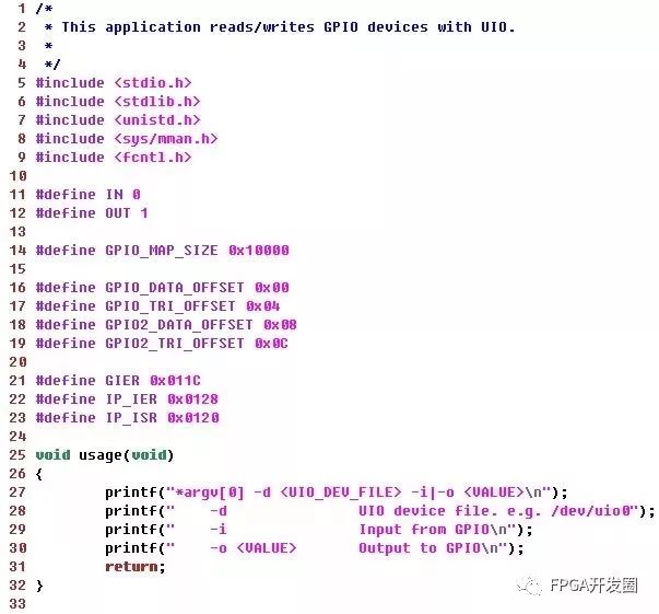
The UIO driver exposes the device memory (register space) of the AXI_GPIO IP. The user-space application uses `mmap` to read and write to the registers. According to the AXI_GPIO documentation (pg144-axi-gpio.pdf), the register map includes settings for interrupts and data.
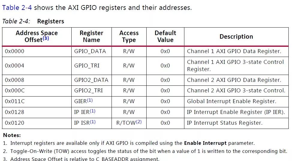
The test application enables interrupts by setting `GIER` and `IP_IER`. The code for this is as follows.

**Testing Process**
During testing, we observed the expected behavior of the UIO driver. While the code might not be perfectly formatted, it demonstrates the core concepts effectively. You can find the full codebase, including hardware files and test applications, on GitHub: [https://gitenterprise.xilinx.com/AlexHe/UIO_Linux_Demo](https://gitenterprise.xilinx.com/AlexHe/UIO_Linux_Demo).
**Experimental Results**
The combination of UIO’s customizable nature and Xilinx’s MPSoC architecture offers a highly flexible platform for embedded applications. Xilinx provides a comprehensive toolchain that streamlines development, making it easier for developers to leverage the power of FPGAs. Although this example is simple, it illustrates the principles behind Xilinx’s "All Programmable" vision and real-world FPGA acceleration applications.
E-cigarette
Shenzhen Yingyuan Technology Co.,ltd , https://www.yingyuanvape.com