
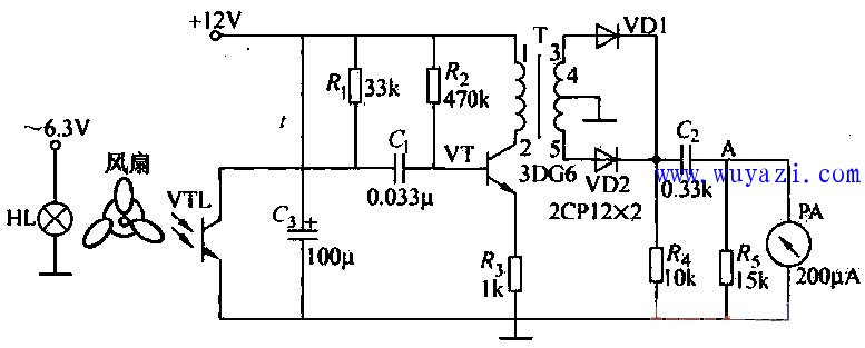
This article explains a circuit designed to measure the speed of an electric fan using a meter. The setup involves placing the fan blades between a light source (such as a bulb) and a phototransistor, as illustrated in the diagram. When a blade blocks the light, the phototransistor is in a high-resistance state, preventing current from flowing. As the blade rotates and creates a gap, the light passes through and activates the phototransistor, causing it to switch to a low-resistance state.
As the fan spins continuously, the phototransistor is triggered three times per revolution—this is typical for a standard table fan with three blades. A 12V voltage is applied across a resistor and the phototransistor in series, generating a pulsed voltage at the phototransistor’s terminals. This pulse signal is then processed by a differentiating circuit composed of the input resistance of a capacitor and the phototransistor, producing a series of sharp pulses.
These pulses are rectified using two diodes, VD1 and VD2, resulting in a double-frequency pulse signal. This signal is then filtered through a capacitor, C2, and sent to a micro-ampere meter. The needle of the meter indicates the fan’s speed—the faster the rotation, the greater the deflection of the needle. This simple yet effective method provides a visual representation of the fan's rotational speed in real time.
The circuit is easy to build and can be used in educational settings or for DIY enthusiasts looking to understand the relationship between mechanical motion and electrical signals. It also demonstrates how optical sensors can be used to detect and measure movement, making it a great example of practical electronics in action.
Liquid Level SensorÂ
Liquid Level Sensor,Liquid Pressure Sensor,Liquid Nitrogen Level Sensor,Liquid Nitrogen Temperature Sensor
Xiaogan Yueneng Electronic Technology Co., Ltd. , https://www.xgsensor.com