
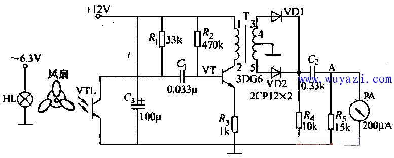
This article explains a practical circuit designed to measure the rotational speed of an electric fan using a meter. The basic idea involves placing the fan's blades between a light source (such as a bulb) and a phototransistor. As the blades rotate, they periodically block the light from reaching the phototransistor. When the blade blocks the light, the phototransistor remains in a high-resistance state, and when it moves out of the way, the light passes through the gap, causing the phototransistor to switch to a low-resistance state.
Since the fan typically has three blades, the phototransistor experiences three cycles of on-off per full rotation. A 12V voltage is applied across a resistor and the phototransistor in series. This setup creates a pulsating voltage at the phototransistor’s terminals due to the intermittent exposure to light. The pulse signal is then processed by a differentiating circuit made up of the input resistance of a capacitor and the phototransistor itself, which converts the pulses into sharp voltage spikes.
These sharp pulses are rectified using two diodes, VD1 and VD2, resulting in a double-frequency pulse signal. This signal is then filtered and sent to a micro-ampere meter. The needle of the meter deflects based on the frequency of the pulses—higher speeds produce greater deflection, while lower speeds result in smaller movement. This method offers a simple and effective way to monitor fan speed visually using basic electronic components.
Digital Laod Cells,Small Load Cell,Hardy Load Cells,Scaime Load Cell
Xiaogan Yueneng Electronic Technology Co., Ltd. , https://www.xgsensor.com