
According to the "Eleventh Five-Year Plan" construction goal, China will fully realize the "village to village" radio and television with more than 20 households and a total of 716,600 electrified natural villages. In June 2008, with the successful launch of Zhongxing No. 9, China’s “village to village†project entered the era of direct broadcast satellites. According to the planning of the State Administration of Radio, Film and Television, based on the current 48 sets of TV programs, a variety of value-added services, such as high-definition and push-on-demand video, will be launched in the future, and the related product manufacturing and service industries will be promoted. With the industrial upgrading, the market scale of hundreds of billions of yuan will be formed to play a positive role in stimulating domestic demand and promoting economic development. In response to the huge demand in this market, Maxim introduced the MAX2119. This paper introduces the reference design of the live star NIM tuner based on Maxim MAX2119 and Zhongtian Lianke AVL1108 demodulation chip.
This article refers to the address: http://
hardware design
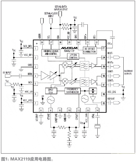
The MAX2119 low-cost, direct-conversion tuner IC is designed for live star set-top boxes in a 5mm x 5mm, 28-pin QFN package. The MAX2119 uses a wideband I/Q downconverter to directly convert satellite signals from the LNB to the baseband, extending the operating frequency range to 925MHz to 2175MHz. The device includes an LNA, an RF variable gain amplifier, an I/Q downconverting mixer, a cutoff frequency programmable baseband lowpass filter, and a digitally controlled variable gain baseband amplifier. The RF and baseband variable gain amplifiers are matched to provide a gain control range greater than 80dB. The MAX2119 includes a complete monolithic VCO and divide-by-N frequency synthesizer. In addition, the on-chip crystal oscillator provides a buffered output for driving additional tuners and demodulators. Synthesizer programming and device configuration via a 2-wire serial interface. The IC automatically selects the VCO (VAS) to automatically select the appropriate VCO. In a multi-tuner application, the device can be configured as one of two 2-wire interface addresses.
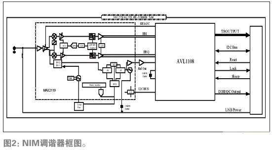
The main functions of the AVL1108 include baseband signal demodulation and channel decoding, which are used to convert the ABS-S baseband signal output from the satellite tuner into a TS stream and provide it to the backend decoder chip through a simple interface. The received signal passes through a matched filter, a symbol clock recovery loop, a carrier frequency and phase tracking loop, an equalizer, and a forward error correction decoder, and then a TS stream is generated and sent to the backend decoding chip. In the 8PSK demodulation mode, the AVL1108 has a satellite channel receiving chip with a symbol rate of 45 MSps and a net stream rate of 120 Mbps, providing more channel reception and high definition television transmission. Through the standard I2C bus control interface, the back-end processing chip can easily control the AVL1108 and configure the down converter (LNB) through the AVL1108å³â”‘è…„iSEqCTM interface. The AVL1108 provides RF automatic gain control that can be connected to the front-end tuner with a simple RC network. The AVL1108 is specifically optimized for the ABS-S signal format for perfect clock synchronization and excellent forward error correction. The AVL1108 integrates a dual-channel, high-performance differential analog-to-digital converter (ADC) with DC, IQ compensation, and phase compensation. The AVL1108 is extremely resistant to phase noise and can quickly lock signals in environments with a frequency offset of 5MHz and maintain accurate clock synchronization.
The MAX2119 requires only one crystal and a small number of resistors and capacitors to form a complete ABS-S receive front end. The ABS-S signal can be directly downconverted to the I/Q signal required by the demodulation chip. The RF input frequency range is from 950MHz to 2150MHz, covering the main working frequency band of 950MHz to 1450MHz of the current live star. The reference frequency of the crystal is 12MHz to 30MHz.
System test
This article only gives the test environment and method of noise figure. For other equipment and specific methods for testing, please contact Maxim engineers.
Noise figure test environment and method
Test Conditions
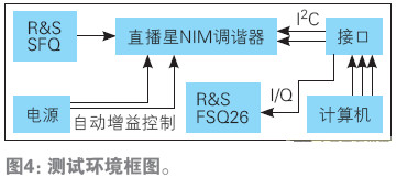
When measuring the noise figure, the input signal power must be carefully calibrated with a power meter and an impedance converter. After calibration, input a -90dBm tone RF signal to the F terminal, and then use the spectrum analyzer to measure the I/Q output and noise spectral density at the I/Q output interface. The noise figure can be calculated by the following formula.
RF frequency = 1550 MHz (single tone signal generated by the signal source)
Input power = -90 dBm (calibrated)
GC1 = 0.5 V
GC2 = +10dB
Line loss = 0.88dB
The value read from the spectrum analyzer:
Output Power (I/Q) = -16.81 dBm
Noise spectral density = -89.51dBm/Hz (noise density)
result:
Noise figure = 174 - (output power - input power) + noise spectral density - 3 - line loss
= 174 – (-16.81+90) – 89.51-3-0.88 dB
= 7.42 dB
Test Results
RF performance
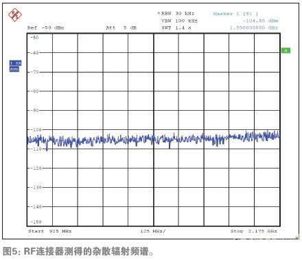
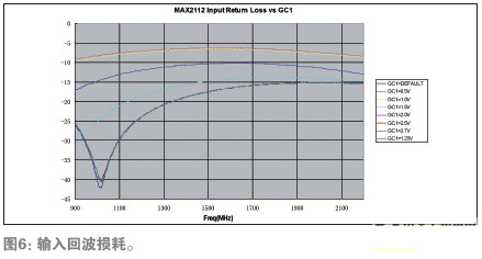
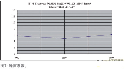
Figure 5, Figure 6, and Figure 7 show the test results of stray radiation, input return loss and noise figure. The stray radiation shown in Figure 5 is lower than -102dBm. The input return loss shown in Figure 6 is 950MHz. The -2150MHz segment is lower than -6.2dB; Figure 7 shows the noise figure in the 950MHz to 2150MHz band, 7.85dB for 950MHz and 8.07dB for 2150MHz. The baseband gain is set to +10dB.
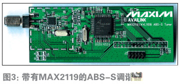
Based on the MAX2119 and AVL108, the ABS-S live star NIM tuner design provides a reference for customers to design a live star set-top box. Customers only need to add part of the decoder chip circuit, Power Supply and front panel to form a complete ABS-S set-top box.
ZhenHuan`s line of ac-dc power supplies output power ranging from 3 W to 200 W is available in a variety of wall plug-in and desktop adapter configurations to meet your needs. From our low power international wall plug adapters to our high power desktop ac-dc power adapters, we ensure that the majority of our external power supplies not only comply with the current energy efficiency Level VI standards, but also meet global safety certifications.
Power Adapter 12V,Ac Dc Adapter,Camera Adaptor,Dc 12V Adapter For Laptop
Shenzhenshi Zhenhuan Electronic Co Ltd , https://www.szzhpower.com