Broadly speaking, Software Defined Radio (SDR) refers to any radio that is part of the signal chain that is software. Specifically, it has some or all of the following characteristics: wideband, multi-band, multi-mode, multi-data rate, software reconfigurable, and its digital conversion (receiving or transmitting) is as close as possible to the antenna. Please note that this description also applies to RF instrumentation such as modern signal (spectrum) analyzers.

It is believed that E-Systems (now Raytheon) of Garland, Texas, built the first software-defined baseband receiver in 1984, and the first software-defined baseband transceiver may be WSC-3 ( v) 9, designed by Patrick AFB in 1987 by E Systems St. Petersburg, Florida. In 1989, HaselTIne and Motorola c. developed the updated radio product Speakeasy for Rome AFB. Modern examples include satellite and terrestrial radio, military joint tactical radio systems (JTRS), and virtually any cellular or land mobile radio terminal or base station.
In theory, for digital conversion and signal processing to work properly, we should have a linear time-invariant system, but practice tells us that connecting a series of analog devices is not so ideal. However, by carefully selecting components and distribution gain, you can maximize the dynamic range of the SDR while maintaining sensitivity. Moreover, the same rules apply regardless of whether the SDR is a communication receiver base station or a signal analyzer.
In some standard communication systems (eg, cellular systems), the SDR operates in a controlled environment, that is, the standard clarifies the requirements for the receiver and transmitter, while the carrier adds margin to the standard. In other systems, such as military, amateur, and land mobile radios, the environment is uncontrolled, that is, the nearest emitter may be next door, and the farthest may be within the whisper of line of sight.
Therefore, before you start designing, you need to make a checklist:
• What are the requirements for the standard?
• What is the minimum and maximum signal level required?
• How much filtering is needed?
• Which image filters, channel filters and anti-aliasing filters are available?
• Does the group delay in the filter cause problems?
• What architecture are you using? Zero-IF, Single, Dual or Triple Conversion • How do you currently generate quadrature signals?
• In the analog or digital (IF sampling) field?
Choosing the ADC itself is worth discussing. The dynamic range of the ADC determines the system architecture (and vice versa). First, we want to look at the signal bandwidth and sampling frequency (the exact frequency of adoption is usually determined by digital signal processing requirements such as clock and/or frame rate). In order to obtain the full-scale SNR of the ADC, especially when sampling high input frequencies, can a sufficiently good clock be generated to sample at the desired frequency without degrading the specified SNR of the ADC? To make the system a linear time-invariant system, the ADC must provide a dynamic range sufficient to support the desired signal, the interfering signal, and the increased margin to support signal fading and AGC response time.
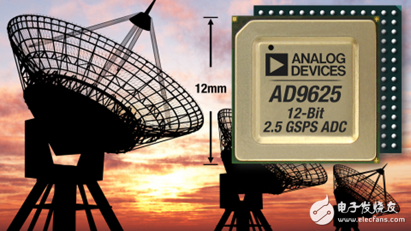
So, what is the dynamic range? The highest performing software-defined radios (and RF lab instruments) typically use 14- to 16-bit high-speed ADCs to sample signals up to 250 MHz at the highest possible frequency. In order to test the widest band of signals according to standards such as alphanumeric combinations such as 802.11, the industry prefers to use a two-channel high-speed ADC such as the 14b AD9680 to positively apply I and Q signals in basebands with I and Q bandwidths equal to or higher than 500 MHz. Sample sampling. Some applications require a smaller dynamic range, so a 12b GSPS ADC (such as the AD9625) is typically used to "grab" a spectrum block with a bandwidth of 500 MHz and an integrated digital downconverter to lower its baseband frequency.
The dynamic range of the ADC is a fundamental trade-off between analog and digital filtering. More analog filtering reduces the amplitude of the interfering signal and the desired range of the ADC. This requires digital conversion of the desired and interfering signals to maintain a linear system. However, analog filtering is not an ideal way, it may have group delay and phase. At the system level, a large number of filtering operations in the analog domain also means that a large amount of expensive mechanical shielding work may be required to maintain filter isolation, and multiple filters may need to be cascaded across multiple IFs to minimize filter filtering. The situation of leakage. In contrast, digital filters have excellent form factor, no leakage, and their characteristics are nearly ideal, but the dynamic range of the ADC needs to be increased to support both signal and interference signals.
The advantages and disadvantages seem obvious, but you must design the receiver to maintain linear input to the ADC under all operating conditions. For example, this requires that you incorporate the AGC's response time into the ADC's headroom, that is, allow a certain amount of dB as a margin to account for input signal changes during the AGC reaction so that the receiver does not change due to signal levels. And there is an overload.
In addition, in UHF and microwave signals, you may also want to add extra margin for signal fading, regardless of whether the signal fading is due to low frequency or environmental conditions such as signals being blocked by buildings or plants. In addition, you need to consider the demodulation of the C/N ratio, adjacent channel and phase channel interference signals, and the margin of the PA feedthrough effect that may occur in a full-duplex system.
Capacitor For Power Transmission And Transformation
Capacitor for power transmission and transformation
New Parallel Capacitor 100Kvar,Capacitor Banks,High Voltage Capacitor Banks,Parallel Capacitor 200kar
YANGZHOU POSITIONING TECH CO., LTD , https://www.yzpstcc.com
