
Keywords: EDMA, DSP, interrupt service routine
1 Introduction Most of the existing TV technology uses interlaced scanning technology, therefore, the digital video signal obtained by directly sampling the entire TV signal, the image information is discontinuous. In modern image processing technology, the gray scale relationship between adjacent pixels in the image is often used for various operations. Therefore, the video signal after A / D conversion must be sorted and formed in the memory. A complete image. EDMA (Enhanced Direct Memory Access) means that in TMS320C6x11 / C64xDSP, without CPU participation, data is transferred between DSP memories. In the system, we first use a piece of FPGA to filter out the non-image information in the digital video signal, and then use EDMA to transfer the processed digital signal from a smaller buffer (such as dual-port RAM) to a larger memory to form a A complete image is processed by the DSP.
2 Set EDMA optional parameter register
2.1 Overview of EDMA transmission parameter group The EDMA transmission parameter group consists of six 32-bit words used to define the EDMA transmission process, including optional parameters, source address, target address, data count, address modification index, link address, etc. Kind of register. The optional parameter register determines the EDMA transmission method. There are 10 control bits in total. The following mainly explains how to set the optional parameter register.
2.2 Set the transmission data unit EDMA to support the storage of 8-bit, 16-bit, and 32-bit data. In this system, 8-bit quantization is used for the gray signal of the image. The external data line of the DSP is 32-bit. The gray values ​​of the 4 pixels are combined into one data unit (element) with a total of 32 bits. Therefore, the ESIZE bit in the register is set to 00b.
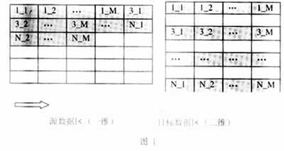
2.3 Set the transmission dimension and address update method The digitized video signal is continuously stored in the buffer (source data area), the address is increased (SUM = 01b), can be regarded as one-dimensional (2DS = 0b). In the target storage area, the image data is stored in rows, and the number of columns in each line is the same as the number of dots in each line of the video signal, so that the storage of the target data area becomes a two-dimensional structure (2DD = 1b). The address is also increasing (DUM = 01b). The line-to-line spacing is the number of bytes required to store a line of TV signal, which can be achieved by setting the FRMIDX register. In this way, as long as the starting addresses of the odd field and even field signals are set to differ by one line, a complete image can be obtained in the target storage area. Figure 1 is a schematic diagram of transmission.
2.4. Set EDMA to generate an interrupt after the end of the transmission. When the video signal fills half of the buffer, the FPGA gives the DSP an external interrupt, which can be any of INT4 to INT7, corresponding to the transmission channel No. 4 to 7 of EDMA. One of the number transmission channels. When the trigger signal arrives, EDMA takes the entire block of data (FS = 1), and at the same time, the video signal is continuously written to the other half of the buffer. Divide the buffer into two halves, read data and write data are not in the same half area, to ensure data integrity.
After the end of a transmission, both the source address and the destination address in the transmission parameter group need to be changed. In this system, the source address and the destination address have many different situations, and the transmission parameter group cannot be changed by link (LINK = 0b) Instead of using the interrupt method, the transfer end interrupt bit TCINT is set to 1. What we use in the system is the INT7 event as the EDMA trigger event, and the transfer end code bit TCC is set to 0111b accordingly. In this way, when the transmission of the corresponding channel 7 ends, the EDMA controller will send an interrupt signal called EDMA INT to the CPU.
3 Interrupt Service Program ISR (Interrupt Service RouTInes)
3.1 The function of the interrupt program If the CPU responds to the interrupt (the default is CPU INT8), it will turn to execute the corresponding interrupt service program. The EDMA transmission parameter group can be changed in the ISR to prepare for the next transmission. The buffer is divided into upper and lower parts, which shows that there are two types of data source addresses, and after each transmission, the source address must be changed to another half area address,
This is a typical ping pong algorithm. Similarly, switching between odd and even fields can also be accomplished with a ping-pong algorithm, which determines the choice of target address.
3.2 Use the DSP / BIOS configuration tool to configure the interrupt function to generate a DSP / BIOS configuration file, add it to the project, open the configuration file, and add the interrupt function to the HWI INT8 item in the HWI subtree of the Scheduling tree. It should be noted that if the configuration file is no longer saved in the directory where the project is located, you must add the -i option to the compilation option to indicate the location of the configuration file, otherwise, the compiler cannot find the definition of the interrupt function.
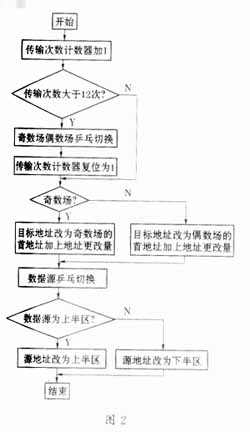
3.3 Algorithm to achieve China's television signal uses the PAL system, each line is 64μs, of which, the image signal occupies 52μs, if using 12.288MHz sampling, each line gets 640 image signals, that is 160 data units, a total of 640 × 8bit data, if two IDT7025 dual-port RAMs are used to form an 8Kbyte × 32bit buffer, then the half area can store 25 lines of digital video signals. That is, when the buffer is filled with 25 lines, the FPGA sends a high-level signal to the DSP external pin INT7 to trigger EDMA to start transferring data. For the convenience of transmission, FPGA is used to write half-line black level to the buffer before the even-field signal arrives. In this way, the number of lines in one field of image is 288 lines. It takes 12 transmissions to transmit one field. When the 13th transmission arrives, the odd field and even field must be switched to change the start address of the target memory.
3.4 Algorithm flow chart The algorithm flow chart is shown in Figure 2.
4 Conclusion Because the on-chip storage space of C6x11DSP is only 64Kbyte, for image processing systems with large data volume, data must be continuously transferred between internal memory and various external memories. EDMA can be used without CPU intervention or reprogramming. Continuous transmission improves the efficiency of the CPU. Therefore, EDMA is called the "backbone" of the secondary storage structure DSP.
Electric Air Mattress,Electric Air Bed,Electric Air Bed Pump,Electric Blow Up Mattress
SHENZHEN NEWO TECHNOLOGY CO,. LTD , https://www.newopump.com