
A triode (full name: a semiconductor triode, also called a bipolar transistor, a transistor) is a semiconductor device that controls current by amplifying a weak signal into an electrical signal having a large amplitude value and also serving as a contactless switch. Introduce the working principle of the triode and the main parameters.
Crystal triodeThe transistor is an organic combination of p-type and n-type semiconductors. The interaction between the two pn junctions causes a qualitative leap in the function of the pn junction and has a current amplification effect. There are two types of crystal triodes, npn type and pnp type, according to the structure. As shown in Figure 2-17. (Represented by Q, VT, PQ) The reason why the triode has current amplification, first of all, two characteristics of the manufacturing process:
(1) The width of the base area is very thin;
(2) The doping concentration of the emitter region is high, that is, the emitter region has a concentration of impurities several hundred times higher than that of the collector region.
How the crystal transistor worksThe necessary conditions for triode operation are: (a) applying a forward voltage between the B and E poles (this voltage cannot exceed 1V); (b) applying a reverse voltage between the C and E poles (this voltage should be The voltage between eb is high); (c) The load must be applied to obtain the output.
When the triode meets the necessary working conditions, its working principle is as follows:
(1) When there is current flowing at the base. Since there is a forward voltage between the B pole and the E pole, electrons move from the emitter to the base, and since a reverse voltage is applied between the C pole and the E pole, electrons moving from the emitter to the base are Under the action of high voltage, the collector enters the collector. Thus, under the action of the positive voltage applied to the base, a large amount of electrons of the emitter are transported to the collector, resulting in a large collector current.
(2) When the base has no current flowing. When a voltage cannot be applied between the B pole and the E pole, since a reverse voltage is applied between the C pole and the E pole, the electrons of the collector are attracted by the positive voltage of the power source to generate a space charge between the C pole and the E pole. The region blocks the flow of electrons from the emitter to the collector, so that no collector current is generated.
In summary, a small base current in the transistor can result in a large collector current, which is the current amplification of the triode. In addition, the triode can also control the conduction and turn-off of the collector current through the base current, which is the switching action (switching characteristic) of the triode.
The principle of the common emitter amplification of the transistor is shown in the figure below:
A, vt is an npn type triode that acts as an amplification.
B, ecc Collector loop power supply (collector junction reverse bias) provides energy for the output signal.
C, rc is the collector DC load resistance, which can be converted into the voltage change amount reflected in the output.
D, the base power supply ebb and the base resistance rb, on the one hand, provide a forward bias voltage for the emitter junction, and also determines the base current ib.
The functions of E, cl and c2 are DC-coupled AC coupling capacitors.
F and rl are AC load equivalent resistors.
AC path: ui positive end - cl-vtb-vtc-c2-rl-ui negative end.
(1) In the daily use, two sets of power supply are inconvenient, and one set of power supply can be used.
(2) To simplify the circuit, the end point of "UCC" and "ground" are used to indicate the DC power supply.
(3) The common terminal of the input signal voltage, the output signal voltage, and the DC power supply is referred to as "ground" and is represented by the symbol "丄", and the ground terminal is used as a zero potential reference.
Voice-over: We can imagine or understand the principle of amplification of the triode by the relationship between the tap and the drain. The schematic diagram is shown in Figure 2-20 below:

Figure 2-20 Reference diagram of the principle of triode amplification
1 As shown in Figure 2.20 (a): When the emitter junction has no voltage or the applied voltage is below the threshold voltage, the water does not flow out of the faucet through the nozzle when the gate is closed. At this time, the resistance between ec is infinite, and the current between ec is off, or the OFF state of the switch.

Figure 2-20 Reference diagram of the principle of triode amplification
2 As shown in Figure 2.20 (b): When the voltage applied to the emitter junction is within the threshold voltage range (about 0.7V for the silicon tube), the gate is loosened a little, and the water flowing from the bottom of the faucet through the nozzle is ticking. status. At this point, the resistance between ec also drops a little.
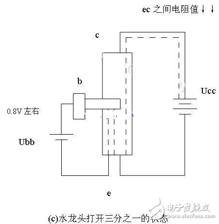
Figure 2-20 Reference diagram of the principle of triode amplification
3 As shown in Figure 2.20 (c): When the voltage applied to the emitter junction is 0.8V, equivalent to one-third of the gate opening, one third of the water at the bottom of the faucet can flow out through the nozzle. At this time, the resistance between ec is also reduced by one-third, and the current between ec is regulated or amplified.
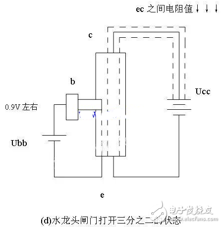
Figure 2-20 Reference diagram of the principle of triode amplification
4 As shown in Figure 2.20 (d): When the voltage applied to the emitter junction is 0.9V, equivalent to two-thirds of the gate opening, two-thirds of the water at the bottom of the faucet can flow out through the nozzle. At this time, the resistance between ec is also reduced by two-thirds, and the current between ec is regulated or amplified.
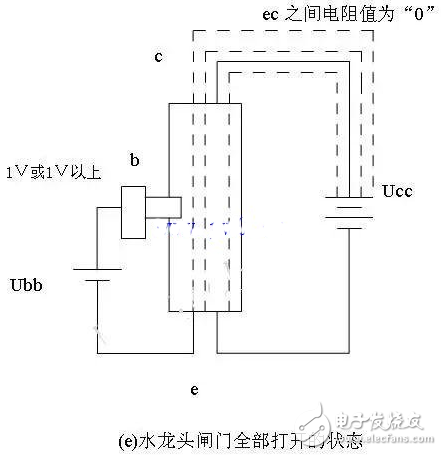
Figure 2-20 Reference diagram of the principle of triode amplification
5 As shown in Figure 2.20 (e): When the voltage applied to the emitter junction is above 1V or 1V, when the gate is fully open, all the water at the bottom of the faucet can flow out through the nozzle. The resistance value between ec also drops to “0â€, or is small, can be or slightly ignored, and the current between ec is saturated, or the ON state of the switch.
Phone Holder,Phone Holder For Mobile Phone,Car Air Vent Phone Holder,Mobile Phone Holder
Shenzhen ChengRong Technology Co.,Ltd. , https://www.chengrongtech.com