
An asynchronous motor is an AC motor that is mainly used as a motor. When the asynchronous motor is running, there is relative motion between the rotating magnetic field in the air gap and the rotor winding. The electromagnetic induction acts to induce current in the rotor winding to generate electromagnetic torque, thereby realizing the conversion of electromechanical energy. Since the rotational speed of the rotor is not equal to the rotational speed of the rotating magnetic field, it is called an asynchronous motor. Because its rotor current is generated by electromagnetic induction, asynchronous motors are also called induction motors.
In terms of electromagnetic relationship, asynchronous motors and transformers are very similar. The stator winding of an asynchronous machine is equivalent to the primary winding of the transformer, and the rotor winding is equivalent to the secondary winding of the transformer. Therefore, it is relatively easy to learn asynchronous motors on the basis of learning the transformer.
First, the main purpose and classification
Asynchronous motors are the most used electric motors in industry and agriculture. Their capacities range from tens of watts to several thousand kilowatts. They are widely used in various industries of the national economy.
For example, in the industrial sector: small and medium-sized rolling mills, various metal cutting machine tools, light industrial machinery, hoists and ventilators on mines are all driven by asynchronous motors.
In agriculture: pumps, threshers, shredders and other agricultural and sideline products processing machinery are also driven by asynchronous motors.
In addition, asynchronous motors are used in many people's daily lives, such as electric fans, freezers, and various medical machines. In short, asynchronous motors have a wide range of applications and large demands. With the development of electrification automation, it plays an important role in industrial and agricultural production and people's lives.
Asynchronous motors can also be used as generators, but are generally only used in special cases.
Asynchronous motors are so common because of their simple construction, ease of manufacture, low cost, ruggedness, and high efficiency and applicable operating characteristics.
However, asynchronous motors also have their disadvantages. Asynchronous motors must absorb backward reactive power from the grid, so its power factor is always less than one. Since the asynchronous motors are the most in the load of the power grid, the reactive power that they need to lag behind is a heavy burden to the power grid, which increases the loss of the transmission process and hinders the output of the active power. When the motor required for the load has a large single unit capacity and the grid power factor is relatively low. It is best to use a synchronous motor to drag.
The asynchronous motor is divided according to the phase number of the stator winding: a single-phase asynchronous motor and a three-phase asynchronous motor. In the absence of three-phase power or the required power is very small, a single-phase motor should be used. The power of a single-phase motor is generally not more than 3 to 4 kW, which is used more in daily life. In industrial and agricultural production, the vast majority use three-phase asynchronous motors.
There are two basic types of three-phase asynchronous motors. One is a squirrel-cage asynchronous motor whose rotor winding is shaped like a cage.
In the squirrel-cage asynchronous motor, it is divided into single squirrel cage, double squirrel cage and deep trough type; the other is the wound-wound asynchronous motor, whose rotor winding and stator winding are basically the same, and also the three-phase winding. Can be joined into a star or a triangle.
Second, the basic working principle and operating status When the stator of the asynchronous motor is connected to the three-phase power supply, three-phase current flows through the stator, and the stator current generates a series of air-gap rotational magnetic density. The main function of this is to rotate the magnetic density of the fundamental wave air gap rotating at the synchronous speed and along the phase sequence of the winding. The size of the synchronous speed determines the frequency of the sub-grid and the number of winding pole pairs, ie ![]() .
.
Figure 5-1(a) is a schematic diagram of a two-pole asynchronous motor. The n1 arrow indicates the direction of rotation of the air gap magnetic density. The largest circle on the innermost side represents the rotor. Two small circles represent the conductors of the rotor winding. The rotor has not yet turned up. The air gap is rotated and magnetically densely represented by N and S poles. At the instant shown in the figure, the N pole is above and the S pole is below.
Thus, the rotor conductor cuts the air gap to rotate the magnetic density to induce the potential, and its direction is as shown in [Picture] and ⊙ in Figure 5-1. Since the rotor winding is short-circuited, there is current in the rotor winding. At the instant shown in Figure 5-1, the direction of the current in the conductor is assumed to be in phase with the induced potential.
According to the polarity and current direction of the air gap rotating magnetic density, it can be seen by using the left-hand rule that an electromagnetic torque in the same direction as the air gap rotating magnetic density acts on the rotor. If this electromagnetic torque can overcome the load torque applied to the rotor, the rotor can rotate and accelerate the rotation. As long as the rotational speed of the rotor is lower than the synchronous rotational speed, the induced potential and the current direction in the rotor conductor are constant, and the direction of the electromagnetic torque is also constant, which is the torque of the driving property.
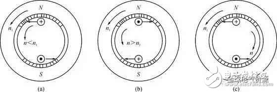
(a) electric motor; (b) generator; (c) electromagnetic brake
Figure 5-1 Three operating states of an asynchronous motor
If the rotational speed of the rotor is accelerated to be equal to the synchronous rotational speed n1, there is no relative motion between the rotor winding and the air gap rotating magnetic density. Of course, the rotor winding no longer senses the potential, and the current and electromagnetic torque are all equal to zero. This means that this situation cannot be sustained.
However, as long as n < n1, there is relative motion between the rotor winding and the air gap rotating magnetic density, and there is current in the rotor winding, and electromagnetic torque acts on the rotor. When the electromagnetic torque is equal to the load torque, the rotor operates at a constant speed. In this case, the stator side absorbs the active power from the power source. This is the simple operating principle of asynchronous motors. It can be seen that the rotational speed n of the asynchronous motor rotor cannot reach the synchronous rotational speed n1, and is generally always slightly smaller than n1, and the asynchronous word is thus derived.
Usually, the ratio of the difference between the synchronous speed and the rotor speed of the motor to the synchronous speed is called the slip (also called slip or slip), which is denoted by s. The slip rate is defined as:

s is a quantity without a unit that is sized to reflect the speed of the motor rotor. For example, when n=0, s=1; when n=n1, s=0; when n>n1, s is negative; when the steering of the motor rotor is opposite to the air gap rotational magnetic density, s>1.
If the motor is driven by another prime mover, the speed of the motor is higher than the synchronous speed n1, that is, n>n1. At this time, the direction of the potential and current in the conductor and the direction of the generated electromagnetic torque are reversed, as shown in Fig. 5. -1(b). In this case, the electromagnetic torque is a braking torque for the prime mover. To keep the rotor of the motor moving, the prime mover must input mechanical power to the motor.
Thus, the stator aspect of the asynchronous machine is changed from the absorption of electrical power from the grid to the transmission of electrical power to the grid, ie in the operating state of the generator.
If other mechanical drive motor rotor is rotated in the opposite direction of the air gap rotation magnetic density, that is, s>1, as shown in Figure 5-1(c). At this time, the direction of the potential and current in the rotor is still the same as that in the working state of the motor, and the direction of the electromagnetic torque acting on the rotor is still consistent with the direction in which the air gap is rotated and magnetically dense, however. The opposite of the actual steering of the rotor. It can be seen that the electromagnetic torque at this time is opposite to the direction of the torque that the dragging machine adds to the rotor of the motor, and the electromagnetic torque is the braking torque. We call this situation the motor is in the electromagnetic brake operating state.
In addition to absorbing the mechanical power of the dragging machine, the motor also absorbs electrical power from the grid. These two parts of the power are finally converted into heat energy by the loss inside the motor.
Third, the structure The main structure of the asynchronous motor is composed of two parts, the stator and the rotor. The stator and the rotor are air gaps. In addition, there are end caps, bearings, bases and other components, Figure 5-2 is a structural diagram of a three-phase squirrel cage asynchronous motor.
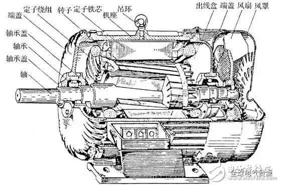
Figure 5-2 Structure of a three-phase squirrel cage asynchronous motor
Stator
The stator is the stationary part of the asynchronous motor. It consists of a base, a stator core and a stator winding.
The base is the outer casing of the motor and acts as a support motor, usually cast in cast iron. The large base is also welded with steel plates.
The stator core is part of the magnetic circuit of the motor and is mounted inside the base. It is a hollow cylinder, the outer wall is matched with the base, the inner wall is slotted, and the stator winding is placed in the slot. In order to reduce the loss in the core, the stator core is laminated with a 0.5 mm thick silicon steel sheet.
The stator windings of the three-phase asynchronous motor are not all connected by the star connection, and only when the large capacity and high voltage are used, the star connection is connected. Generally, medium and small capacity low voltage asynchronous motors usually take out the six wire ends of the three-phase winding and connect them to a triangle or star connection as needed. In this way, the motor can be applied to two different levels of power supply voltage, such as star connection for 380V power supply; triangle connection can be used for 220V power supply, and can meet the requirements of starting, that is, designed to be connected in delta When the method is used, it is used for the 380V power supply. When starting, it is changed to the star connection method to achieve the purpose of step-down starting.
The stator winding is wound with an insulated copper wire embedded in the stator slot, and the winding is separated from the groove wall by an insulating material.
Air gap
The air gap of an asynchronous motor is much smaller than that of a DC motor of the same capacity. In medium and small asynchronous motors, it is generally 0.2 to 1.0 mm. This is because the excitation current of the asynchronous motor is supplied by the grid. When the air gap is large, the excitation current is also large, thereby reducing the power factor of the motor. In order to improve the power factor, the air gap should be made smaller. However, if the air gap is too small, the assembly will be difficult, the operation will be unreliable, and the higher harmonic magnetic field will be enhanced, thereby increasing the additional loss.
3. Rotor
The rotor of the motor consists of a rotor core, a rotor winding and a rotating shaft. The rotor core is also a part of the magnetic circuit, which is generally formed by stacking silicon steel sheets, and the iron core is fixed on the rotating shaft.
If the rotor winding is wire-wound, it can be joined in a star or a triangle. Generally, the small capacity is connected into a triangle; the medium and large capacity are connected in a star shape. The three lead wires of the winding are connected to three collector rings (the collector ring is fixed on the rotating shaft), and are led out by a set of brushes, as shown in Figure 5-3.
This allows the external resistor to be connected to the rotor winding loop. The purpose of the string resistor is to improve the characteristics of the motor or to adjust the speed.
The structure of the squirrel-cage rotor winding is quite different from that of the stator winding. There is also a groove on the rotor core, and each groove has a guide bar. There are two return rings at the two ends of the iron core, and the portions of all the guide bars extending out of the slots are respectively connected to form a short circuit. If the rotor core is removed, the winding is shaped like a rat cage, as shown in Figure 5-4(a). The material of the guide strip is made of copper and is useful for aluminum. If copper is used, insert the bare copper strip prepared in advance into the rotor core slot, and then use a copper ring to cover the ends of the copper strips at both ends and weld them together; if it is made of aluminum, it is The molten aluminum liquid is directly cast into the rotor core groove, and the reed ring and the fan blade are cast once, as shown in Fig. 5-4(b).
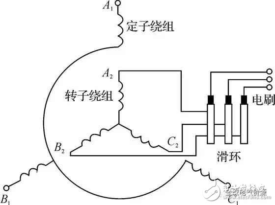
Figure 5-3 Wiring diagram of the stator and rotor windings of the wound asynchronous motor
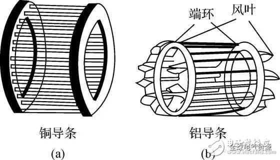
(a) copper strip winding; (b) cast aluminum rotor
Figure 5-4 Squirrel cage rotor winding
Fourth, the ratingThe rating of an asynchronous motor is usually indicated on the nameplate and includes the following:
(1) Rated power PN: refers to the mechanical power output by the motor on the rotating shaft during rated operation, the unit is dry tile.
(2) Rated voltage UN: refers to the line voltage applied to the stator winding under rated operating conditions, in volts.
(3) Rated current IN: The motor is rated voltage on the stator winding. When the rated power is output on the shaft, the line current in the winding is determined, and the unit is ampere.
(4) Rated rate f: The frequency of industrial electricity in China is 50 Hz.
(5) Rated speed nN: refers to the rated voltage of the motor stator plus rated frequency, and the speed of the motor when the rated power is output on the shaft, the unit is rpm.
(6) Rated power factor cosφN: refers to the power factor of the stator side of the motor at rated load.
(7) Insulation class and temperature rise.
|
*These Xbox Series X battery is rechargeable battery pack, specially designed for your Xbox series X/S controller, 2 pieces of 800mAh Ni-MH battery and 1 piece of USB-C charging cable,no need any charging dock can save room and there is no need to worry about the storage of AA batteries.
* The X/S controller is protected from overcharge and power surge, ensuring the safety of charging at night.
* Can play when charging, no need to worry the controller power off, bring you great experience during games Rechargeable battery pack for Xbox Series X S controller, Fully charged is around 3-4 hours and provides up to 12 hours of playtime.it comes with the type-C cable, no extra adapter required. A GREEN light means charging, RED light means fully charged.
|
|
|
Product Name
|
Rechargeable Battery for Xbox Series X
|
|
weight
|
130g
|
|
Input
|
TYPE-C 5V
|
|
Output
|
DC2.4-3.0V
|
|
Product color
|
Black
|
|
Charging time
|
about 2 hours
|
|
play time
|
about 10 hours
|
|
OEM/ODM
|
warmly welcome
|
|
Advatage
|
100 QC test before shipping
|


Xbox Series X Battery,Rechargeable Xbox Series X Charge Kit,Xbox Series X Rechargeable Battery Pack,Xbox Series X Battery Pack
Shenzhen GEME electronics Co,.Ltd , https://www.gemesz.com