
In recent decades, resource shortages and environmental protection have become two major challenges facing the world's automotive industry. The shortage of petroleum resources and the pollution of automobile exhaust to the atmosphere are becoming more and more serious. Therefore, the automobile industry of all countries has increased the research and development of other fuel vehicles and electric vehicles.
1 Hybrid electric vehicle system structure
Figure 1 shows the topology of a series hybrid system. The whole hybrid system adopts a series structure, which is mainly composed of three parts: energy supply system, electric drive system and mechanical transmission system. The energy supply system is composed of a power battery pack and an engine-generator unit; the electric drive system is composed of an inverter and an electric motor; the mechanical transmission system sends the mechanical output of the motor to the transaxle through the reducer. The vehicle system uses the can bus to transmit information and commands, and the communication medium uses shielded twisted pairs.
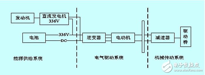
Figure 1 Series hybrid system topology diagram
2 motor drive system main circuit structure
2.1 Main circuit component selection
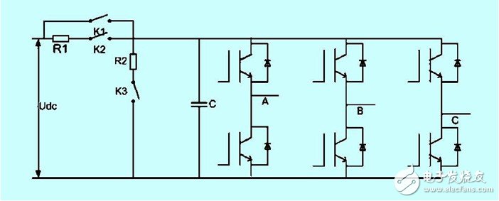
Figure 2 drive system main circuit circuit diagram
The main circuit principle of the motor drive system is shown in Figure 2. The three-phase bridge inverter is used according to the parameters of the traction motor: rated power 50kw; rated current 167a; rated voltage 240v; rated frequency 200hz; peak frequency 400hz. The power device is available with 600v/600a and a switching frequency of 10khz.
The DC side supporting capacitor is formed by connecting three 3300μf electrolytic capacitors in parallel and connected in parallel at both ends of the high voltage DC bus. Since the DC side voltage udc=336v, the withstand voltage rating of the supporting capacitor should be higher than 336v, taking 450v.
3 control circuit
3.1 Drive system control part design
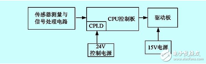
Figure 3 Motor drive system control block diagram
Figure 3 is a block diagram of the motor drive system control, which consists of sensor measurement and signal processing circuit, control board and driver board.
The motor control circuit is divided into a motor voltage control circuit (power amplifier circuit and H-type bipolar drive circuit) and a PWM pulse width modulation circuit. The anti-interference circuit and the over-voltage detection and protection circuits have been embedded in the two modules of the motor voltage control circuit and the PWM pulse width modulation circuit.
P WM pulse width modulation circuit

Figure 4 Schematic diagram of PWM pulse width modulation circuit
The design basis is as follows: UC 3 637 control voltage (16-terminal) When ± 5V changes, the voltage processed by the UC 3 637 internal proportional amplifier (ie, the ends of pins 9, 1 1) varies between 2 and 8V and Linearity is better.
Smart down light with both warm light and RGB colorful light, it can meet the daily lighting and ambient lighting, high efficiency and energy saving, light source is stable and without strobe. Three color temperatures can be choosed for white lighting, 3000K, 4000K and 65000K. The color, brightness and RGB lighting auto-cycle mode can be controlled on the App. Three sizes of down lights for customer`s choice, small , middle and big sizes can meet different requirements, and the installation is very easy.

Product Parameters
Working Voltage: AC110-240V
Frequency: 50-60HZ
Lamp Power: 9W
Lumen: 805LM
Color: RGB+CCT
Protocol: Bluetooth Mesh
Wireless Transmission: 20m
Control Way- Smart APP Control
The light color, brightness, cycle mode and timing can be controlled by App.The App are developed on the most advanced Bluetooth Mesh technology. [LinkupHome" App can be downloaded in the App store or Google Player, then you can control our product without any complicated steps. The App is stable, easy control and multifunctional.


Smart Technology- Bluetooth Mesh
The advantages of Bluetooth Mesh are fast connect, low power consumption, no password required and Ad-Hoc Network. No need WIFI and hubs, as long as you have a Bluetooth-enabled smart phone, you can experience the smart light. When you install several smart down lights, the self-organizing network function can make the signals free connect, break the limitation of distance.

Smart Down Light,Smart LED Downlight,Smart Economic Downlight,Smart Home Down Light
Ningbo Homey Photoelectric Technology. Co., Ltd , https://www.linkuphome.com