
1 Introduction
Functional switches play an important role in people's production and life. Various types of automatic power-off switches and voice-activated switches and infrared sensor switches are widely available in the market.
At present, the research on the call power-off switch involves two main aspects: one is to directly use the series-parallel relationship of the switch and the function of the relay to realize the automatic power-off function of the call after power failure. The cost of the solution is lower, but the switch volume is larger; The second is to use digital circuits for programming to achieve automatic power-off, stable switching performance, small size, but high cost. Domestic and foreign research on infrared sensor switches is relatively mature. Generally, BISS0001, CSC9803 and other chips are used to process the received infrared sensing signals. These chips are powerful but have many chip pins and complicated peripheral circuit connections. Although the above two switches have already had some related invention patents in China, there is no energy-saving switch that combines the two functions. So we designed a kind of infrared call power-off automatic energy-saving switch that combines the above two switch functions. It uses two relays in series to realize the call power-off function, and uses LM324 chip to process the infrared induction signal, making the switch volume smaller. The cost is lower; fill the gap in the field in China and respond to the call for energy conservation. This kind of switch can be used in students' bedrooms, homes and other places.
2. Circuit schematic and design
The block diagram of the switch function implementation is shown in Figure 1.
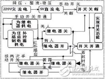
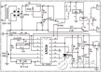
The overall design of the switch is to control the high voltage (220v) part with a low voltage (5v), and the low voltage is obtained by a high voltage transformer process. The switch is mainly composed of a power supply part, an infrared sensing control part, and a relay control part. The circuit schematic of the switch is shown in Figure 2.
(1) Design of the power supply part
In Fig. 2, the 220V AC power is outputted by the transformer circuit with a 12V AC voltage, which is rectified by a bridge rectifier circuit composed of IN4001. After that, it is filtered by 1000uf capacitors, and then stabilized by 7805 to finally obtain a stable voltage of 5V across the capacitor C2.
And this 5V stable voltage can provide the working voltage for the infrared sensing signal control part.
(2) Infrared sensor head section
In Figure 2, LHI907 is a pyroelectric (pyroelectric) human body infrared sensor head. About 10 um of infrared rays emitted by the human body reach the pyroelectric element, and when the temperature of the infrared radiation received by the human body changes, the charge balance is lost and the charge is released outward. The sensor itself does not emit any type of radiation, the device consumes little power, is concealed, and is inexpensive. The sensitivity of the infrared pyroelectric sensor to the human body is also highly dependent on the direction of motion of the person. Infrared pyroelectric sensors are the least sensitive to radial movement reactions and most sensitive to cross-cutting movements, which can only detect moving humans.
(3) Processing of infrared sensing signals
The S-side signal input of the LHI907 is integrated with the No. 3 pin of the operational amplifier LM324. The negative feedback amplification of the first two operational amplifiers puts the signal about 100 times, and then the other is input to the other op amp via the 10th pin. Comparison. When there is no one, the 8 pin outputs a high level. When there is a bit, the 8 pin outputs a low level, and then the 13 pin is connected to the operational amplifier for the RC delay. When pin 8 is high, pin 13 is high. The voltage of op amp 4 is compared to output low level at terminal 14. When pin 8 is low, capacitor C7 is discharged through IN4001. At this time, 13 pin is Low level, 14 feet is high level, then 8 feet immediately change back to high level, then the power supply is charged to C7, 13 feet are still low level, after charging is finished, 13 feet become high level, 14 feet Goes low. This time delay function test measures about 30 seconds, during which there is human body activity and refresh delay time. This time delay design solves the problem that the pyroelectric sensor can only sense the movement of the human body, thereby prolonging the time of the output signal, and can adjust the size of the C7 to different delay times according to different occasions.
(4) Relay control section
In Figure 2, K1 and K2 are normally open relays. Since the power supply part is high voltage alternating current, the control part is low voltage direct current. In the figure, the triode adopts 9014. Its function is to control the working state of relay K2 through the input signal of 14 pins of LM324. The signal of the pin cannot directly drive the K2 work, so the 9014 design is still necessary.
(5) Peripheral circuit of the switch
The nodes P1, P2, P3, and P4 in FIG. 3 correspond to the P1, P2, P3, and P4 nodes in FIG. 2, so that the switch can control the extinguishing and extinguishing states of the light bulb, thereby achieving the purpose of energy saving.
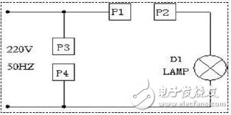
Figure 3 switch peripheral circuit
3. The overall circuit works
A state: When the circuit is connected correctly and works normally, the switch is connected to the D terminal of LHI907, and the relay K1 works to make the contact open. At this time, the power supply is powered by the human body infrared sensing circuit, and the infrared sensor works normally, and can pass the detection. There is no one to control the action of relay K2. At this time, the manual switch SW can directly cut off the power supply part of the infrared induction once, thereby unconditionally terminating the operation of the relay K2, and once again operating the SW, it can switch to the infrared monitoring state.
B state: When the working state is at the breakpoint, the relay K1 stops working and calls again. The relay K1 cuts off the power supply of the 9014 triode collector, so the relay K2 does not work. When the SW operates once, K1 works to realize the self-protection function of the relay. Move SW again to return to the working state in A. Thereby, the function of automatically powering off the call after the person is off and the power is turned off is realized, and the function of saving electric energy is achieved.
4. Analysis of results
Make the actual circuit and measure the operation of the lamp in each state of the switch as shown in Table 1:
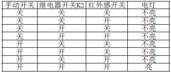
(Note: the status of someone close to the infrared sensor head is recorded as the infrared sensor switch open state, the state of the person leaving the infrared sensor head is recorded as the infrared sensor switch off state; after the power failure, the state of the relay k2 is recorded as the off state state, and the relay k2 state after the call is made. Recorded as open state.)
Therefore, the entire switch realizes the function of "the person is off the light, the person is lit" and the function is automatically disconnected after the power is turned off.
5 Conclusion
This paper designed a new type of switch - a switch that combines the functions of a common human body infrared sensor switch and a call power switch. At present, there is no switch that has such a switch function in China, and its production cost is low, and the application prospect is good; it can be used in student dormitory, but also in homes, office places, etc., and is convenient to install. Through a large number of practical use proofs, as long as the installation position of the infrared sensor head is appropriate, the switch can work normally and reliably, and plays the role of energy saving and power failure protection.
The Hair Dryer is a combination of a set of electric heating wires and a small high-speed fan. When energized, the heating wire generates heat, and the wind blown by the fan passes through the heating wire to become hot air. If only a small fan rotates and the heating wire is not hot, then only the wind will blow out but not the heat.
Cordless Hair Dryer has the function of anti-leakage protection, safety, dexterity, lightness, low noise, etc. It can also solve the problem of dry burn and hot when blowing hair, so that you can avoid the trouble of cold and wet hair washing in autumn and winter.
The wind blown by the Portable Hair Dryer is dry. If it is used for too long, it will easily cause moisture loss and heat damage. The secret to minimize the damage is: pat the moisture on the hair first with a towel and gently hand Comb your hair and then use the hair dryer.

Hair Dryer
Cordless Hair Dryer,Hooded Hair Dryer,Travel Hair Dryer,Portable Hair Dryer
Taishan Jie Da Electrical Co., Ltd , https://www.ts-jieda.com