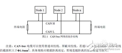
CAN, short for "Controller Area Network," is a widely used fieldbus in industrial and automotive applications. As a multi-master serial communication bus, CAN is designed to support high data rates and strong electromagnetic interference (EMI) immunity. It also has the capability to detect errors on the communication line, ensuring reliable data transmission. Even over long distances of up to 10 kilometers, CAN can maintain a data rate of up to 50 kbit/s. Table 1 illustrates the relationship between the maximum distance between any two nodes on the CAN bus and the corresponding bit rate.

The CAN bus utilizes terminating resistors for two main purposes:
**First, it enhances the bus's anti-interference capability and ensures that the bus quickly transitions into the recessive state.**
**Second, it improves signal integrity.**
In the CAN bus, there are two signal states: "dominant" and "recessive." Dominant represents a logic '0,' while recessive represents a logic '1.' These states are determined by the voltage levels on the CANH and CANL lines. A typical CAN transceiver is shown below, with its internal structure and connections to the CAN bus.

When the bus is in the dominant state, internal transistors Q1 and Q2 are turned on, creating a voltage difference between CANH and CANL. In the recessive state, these transistors are off, and the voltage difference between the lines is zero. Without proper termination, the bus may be susceptible to external noise, as even small energy disturbances can cause a transition to the dominant state. To prevent this, a differential load resistor is often added between CANH and CANL. This resistor helps reduce the impact of external signals and ensures the bus returns to the recessive state more reliably.
During the transition from dominant to recessive, parasitic capacitance on the bus must be discharged. If no load resistor is present, the discharge occurs only through the internal resistance of the transceiver, which can be slow. This delay can lead to communication issues, especially at higher bit rates or with longer cables. Adding a 60Ω resistor significantly reduces the time required for the bus to return to the recessive state, improving overall performance.


Another important function of the terminating resistor is to improve signal quality. When a signal edge encounters an impedance mismatch, reflections can occur, causing signal distortion or ringing. These reflections can interfere with communication, especially at higher speeds. By placing a resistor at the end of the bus that matches the cable's characteristic impedance, the reflected energy is absorbed, reducing signal distortion.
A simulation test using a 1 Mbit/s bit rate showed that without termination, the signal waveform had noticeable ringing on the rising edge. After adding a 120Ω resistor at the end of the twisted pair, the signal improved significantly, with ringing eliminated.


In a straight-line configuration, both ends of the cable should have terminating resistors to ensure proper signal matching and minimize reflections.
Why 120Ω?
The characteristic impedance of a cable can be determined experimentally by connecting one end to a resistor and observing the signal waveform. Adjust the resistance until the signal appears as a clean square wave without ringing. The value at this point corresponds to the cable’s characteristic impedance. Most twisted-pair cables used in CAN systems have a characteristic impedance of around 120Ω, which is why this value is commonly recommended for termination.
Notes:
(1) Both ends of the CAN bus should have a 120Ω resistor connected between CAN_H and CAN_L. However, in practice, a 60Ω jumper resistance is often sufficient.
(2) When not in use, pin RX1 of the SJA1000 can be grounded. With the CDR.6 setting, the bus length can be extended significantly.
(3) The levels of TX0 and TX1 determine the output level, and their behavior depends on the settings of the output control register (OCR).
(4) The RS pin of the AT82C250 is indirectly connected to ground via a slope resistor. Its value can be adjusted based on the bus speed, typically ranging from 16kΩ to 140kΩ.
(5) The MAX232 requires four electrolytic capacitors (C1, C2, C3, C4), each rated at 1μF/25V. Tantalum capacitors are preferred, and they should be placed close to the chip. A 0.1μF decoupling capacitor should also be connected between VCC and ground.
The EI 28 Transformer is a specific type of transformer featuring an EI-laminated core structure, commonly used across various industries including power, electronics, instrumentation, lighting, and audio.
Basic Information
Model: EI 28
Type: Single-phase transformer with an EI-type iron core
Cooling Method: Dry-type transformer
Winding Configuration: Multi-winding transformer
Certifications: May include international standard certifications such as ISO 9001
Product Features
High Efficiency: The EI 28 Transformer is often designed for high efficiency, thanks to optimized designs and materials used. Some manufacturers employ cold-rolled grain-oriented silicon steel strips for the core, which reduces losses and enhances efficiency.
Low Losses: Compared to traditional transformers, the EI 28 Transformer exhibits lower losses, contributing to energy savings and reduced operating costs.
Low Temperature Rise: During operation, the transformer experiences a low temperature rise, extending its lifespan and improving system stability.
Customization: Many manufacturers offer customization options for the EI 28 Transformer, allowing clients to specify different power ratings, sizes, and appearances based on their unique requirements.
Ei28 Transformer,15V Smd Transformer,28 Volt Transformer,28V Transformer,variac transformer
Guang Er Zhong(Zhaoqing)Electronics Co., Ltd , https://www.geztransformer.com
