Structure and principle design of sugar candied low-pass filter
The candied fruit low-pass filter is a widely used coaxial low-pass filter due to its simple structure, low insertion loss, and high power handling capability. Its design follows the principles of high-low impedance line filters. However, unlike traditional planar structures, the candied fruit low-pass filter is a three-dimensional structure, which introduces significant edge capacitance effects that cannot be ignored. This makes the conventional high-low impedance interconnection model inaccurate for such designs. This article presents a practical and accurate method for designing candied fruit low-pass filters by addressing these challenges.
1. Design Challenges and Countermeasures of Candied Fruit Low-Pass Filters
1.1 Discontinuity Analysis of Candied Fruit Low-Pass Filters
The typical structure of a candied fruit low-pass filter is shown in Figure 1. At lower frequencies, the length of the sugar cane-like elements is relatively large, making the edge capacitance negligible compared to the low-impedance lines. In this case, a basic high-low impedance cascade model can be used to approximate the behavior. However, as the operating frequency increases, the physical size of the structure decreases, causing the edge capacitance to become more significant and no longer negligible. The traditional high-low impedance model becomes less accurate under these conditions. Therefore, accurately modeling the edge capacitance is crucial for improving the design precision.
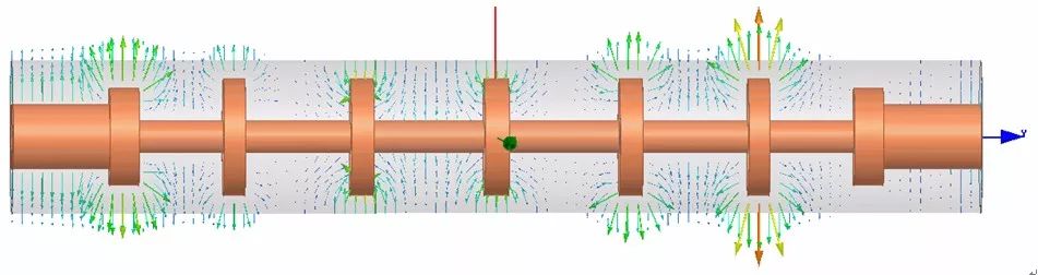
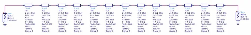
Figure 1: Typical low-pass structure and principle of candied fruit
During the initial analysis of the candied fruit low-pass filter, two main factors were considered:
- Edge capacitance
- Capacitive coupling between the low-impedance lines (as shown in the image below)
Based on this approach, a simulation model was created, and while the results showed a high frequency response, the standing wave ratio was not ideal. Upon examining the field distribution, it was observed that only the edge capacitance field was prominent between the sugar cane-like structures, with minimal plate capacitance (coupling) between the low-impedance lines. This suggests that the low-impedance lines are effectively at the same potential due to their connection with high-impedance lines, thus not forming a capacitor. As a result, focusing solely on the edge capacitance significantly improves the model accuracy. Hence, the primary challenge in modeling the candied fruit low-pass filter is accurately representing the edge capacitance.
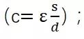
1.2 Acquisition of Edge Capacitance
Edge capacitance arises from the step discontinuity between high and low impedance lines. Typically, the dimensions of these lines are fixed during the design phase. By using a ladder structure in HFSS, a model can be created, and an S2P file can be generated to represent the discontinuity parameters. This S2P file is then imported into ADS to build a circuit model that accurately reflects the performance of the candied fruit low-pass filter.
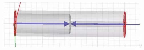
Figure 2: Steps for discontinuity modeling
2. Design Example of Candied Fruit Low-Pass Filter
Based on the above discussion, the design process for a candied fruit low-pass filter can be summarized in three key steps:
- Simulate high and low impedance lines according to the planned dimensions and obtain the step discontinuity parameters.
- Build a model in ADS to extract the necessary size data based on 3D simulation results.
- Construct a 3D simulation model in HFSS to validate the design.
2.1 Size Planning and Simulation of Discontinuity Steps
To illustrate the design process, we use a 15 GHz example. A model parameter table is set up as shown in Table 1.
Table 1: Key Size Planning for Candied Fruit Filters
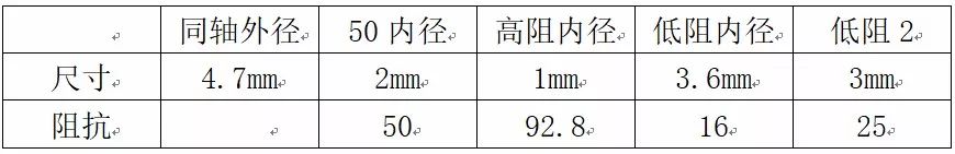
Using the data from Table 1, a discontinuity step model (as shown in Figure 2) is created, and an S2P file is obtained through simulation.
2.2 Building a Model in ADS to Obtain Key Size Data
Following the previous steps, an ADS model is constructed as shown in Figure 4. The discontinuity step is represented using the S2P file. Parameters are adjusted in ADS to achieve the desired frequency response. Detailed results are shown in Figure 3.
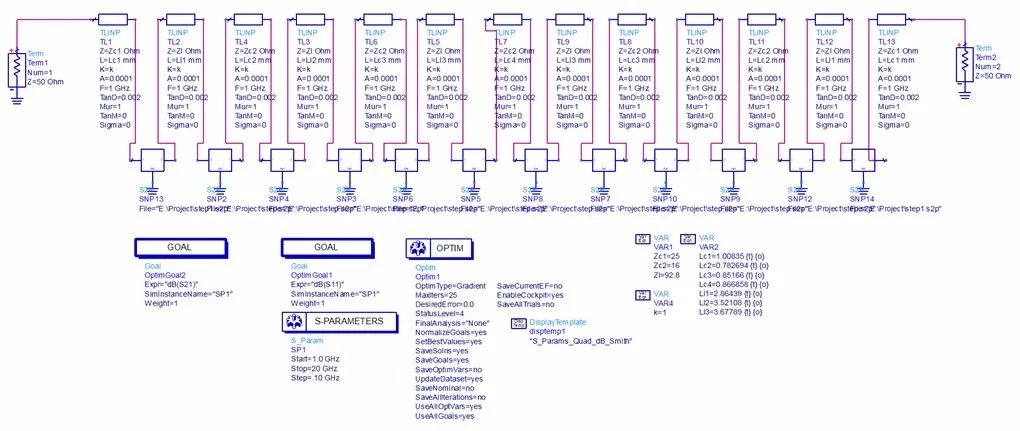
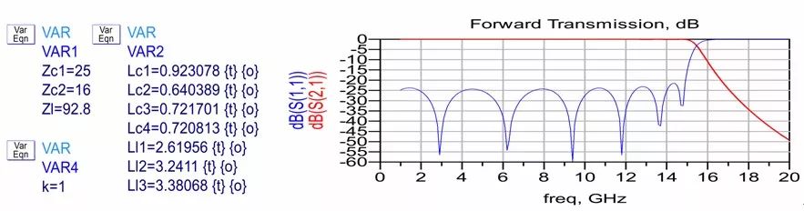
Figure 3: ADS model and simulation results
2.3 Building a Model in HFSS to Validate the Design
Based on the results from the second step, a 3D model is built in HFSS, as shown in Figure 4. The simulation results are very promising, and further optimization is rarely needed. This confirms the accuracy of the ADS-based circuit model.
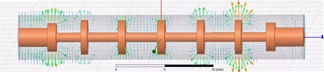
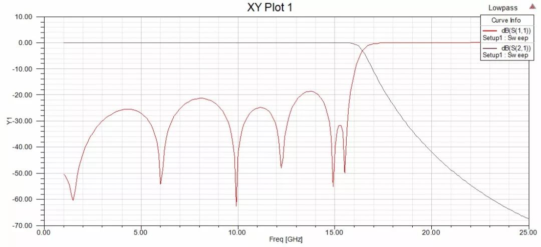
Figure 4: 3D simulation model and one simulation result
Fanless Pc,Intel Nuc Fanless,Fanless Industrial Pc,Nuc Fanless
Guangdong Elieken Electronic Technology Co.,Ltd. , https://www.elieken.com