
Abstract: According to the requirements of the taxi company for the vehicle positioning function, this paper takes the single-chip MSP430F147 as the core, integrates the GPS module and GPRS module, and discusses the design of the taxi GPS positioning system in detail, including the design of the hardware scheme and software scheme. The system can collect real-time location information of the running taxi vehicle in real time, and can send the collected information to the taxi operating company through the GPRS module, which provides convenience for the taxi company to monitor and dispatch the vehicle.
Keywords: single chip microcomputer; GPS module; GPRS module introduction
This article refers to the address: http://
With the rapid development of modern society, taxis, as part of urban public transportation, have become an indispensable means of transport for the general public. However, the accompanying taxi monitoring and dispatching and safety management has become a major problem for every taxi company. How to quickly and conveniently manage the taxis, and monitor the safety status of each taxi in real time. We developed a taxi GPS positioning system for this problem. This system greatly facilitates taxi companies to taxis. Dispatching management, as well as real-time monitoring of taxi location and security status.
Taxi GPS positioning system function
The taxi GPS positioning system is an integral part of the taxi monitoring and dispatching system. It can provide the taxi monitoring and dispatching center with real-time location information of the taxi to ensure the safe operation of the taxi, so as to track the taxi in real time and rent the GPS positioning system. The function is as follows:
1) Information collection function
The GPS positioning system can accurately collect real-time information (such as longitude, dimension, speed, direction, etc.) of the vehicle.
2) The data storage function can store information such as the vehicle ID number, speed information 5 minutes before parking, and continuous travel time.
3) Data transmission function
The collected real-time information of the taxi can be sent to the monitoring and dispatching center through GPRS, so that the monitoring and dispatching center can monitor the location and safety status of the rented vehicle in real time.
System hardware design
The system uses the single chip MSP430F147 as the core controller, integrating GPS module, GPRS module, serial memory module and power management module. The system block diagram is shown in Figure 1.
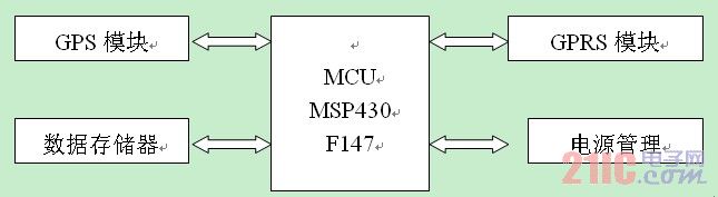
Figure 1 system block diagram
Fig.1 System diagram
2.1 MCU unit
The system adopts TI's MSP430F147 single-chip microcomputer as the core controller [1]. This single-chip microcomputer has a 16-bit CPU integrated register and constant generator, which can realize the maximum code efficiency of the single-chip microcomputer; integrate JTAG and support online programming; Full-duplex serial synchronous/asynchronous communication interface; 6 8-bit I/O ports; external interrupt input interface. The serial port 0 of the single chip microcomputer is responsible for receiving the data information output by the GPS module, analyzing and extracting the valid information data received, on the one hand storing the data, and on the other hand sending the information to the taxi monitoring and dispatching center through the GPRS module.
2.2 GPS module
2.2.1 GPS overview
GPS (Global Positioning System) is a new generation of satellite navigation and positioning system developed by the United States, which can provide global users with continuous, real-time and high-precision three-dimensional position, three-dimensional speed and time information. It is a navigation system with high precision in the world, and has been widely used in military, economic, geographic information measurement and control and other fields. The GPS positioning system consists of three parts: a GPS satellite constellation (space part), a ground monitoring system (ground control part), and a GPS signal receiver (user equipment part).
2.2.2 Introduction to GPS Module
GPS uses the GS-87 module [2], which is a high-performance, low-power intelligent satellite receiving module or satellite receiving engine. It uses the third-generation satellite positioning receiver designed by Sifu SiRF star III. The chip is a complete satellite positioning receiver with full range of functions. The system structure is shown in Figure 2. The GPS Antenna (GPS antenna) receives the satellite signal and converts the weak electromagnetic wave energy into the corresponding current. The current is amplified by the LNA (Low Noise Amplifier), converted by the filter filter, sent to the SIRF StarIII (composed of GRF3W and GSP3) for processing, and the processed signal is connected to the microcontroller through the serial port. The user processes the information received by the GPS through software programming control of the single chip microcomputer, and extracts information useful to the user.
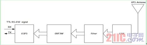
Figure 2 System structure diagram
Fig.2 System diagram
2.3 GPRS module
2.3.1 GPRS Overview
GPRS (General Packet Radio Service) is short for general wireless packet service. It is a wireless packet switching technology based on GSM (Global System for Mobile Communications) system, providing end-to-end, wide-area wireless IP connection; it is GSM Phase2. One of the contents of the specification implementation can provide a higher data rate than the existing GSM network of 9.6 kbit/s. GPRS uses the same frequency band, bandwidth, burst structure, wireless modulation standard, FM rules and the same TDMA frame structure as GSM. Therefore, when building a GPRS system based on the GSM system, only some hardware devices and software upgrades need to be added. The method of constructing the GPRS system: 1) GPRS is implemented on the basis of the existing GSM network, and three main components are introduced in the GSM network: GPRS Service Support Node (SGSN), GPRS Gateway Support Node Point (GGSN, Gateway GPRS Supporting Node) and Packet Control Unit (PCU). 2) Software upgrades to related components of GSM.
GPRS data transmission has the following characteristics:
(1) The communication method of the time-based packet switching technology adopted. (2) According to the data flow fee, not the online time limit. (3) The transmission rate is high. (4) Always online. (5) The GPRS network access speed is fast, providing a seamless connection with the existing data network. (6) GPRS supports applications based on standard data communication protocols, and can be interconnected with IP networks and X.25 networks. (7) GPRS is designed to support intermittent burst data transmission and occasional large data transmission.
2.3.2 Introduction to GPRS Module
The GPRS module uses the MC52i module from Siemens [3], which is an important part of the communication between the GPS positioning system and the taxi company monitoring and dispatching center. On the one hand, the GPRS module can transmit the vehicle positioning information (such as time, longitude, latitude, speed, direction, etc.) collected by the GPS module to the server of the taxi monitoring and dispatching center in real time; on the other hand, it can also receive monitoring from the taxi. Scheduling commands for the dispatch center. Realize two-way communication between the GPS positioning system and the monitoring and dispatching center.
2.3.3 GPRS interface circuit design
The MC52i module is connected to the MSP430F147 through the serial port and the signal control pin. The circuit connection diagram is shown in Figure 3. The 26-30 pins of the MC52i are the input terminals for the supply voltage. The input voltage range is 3.3V to 4.8V and the peak load current is 2A. The TX52 and RXD0 of the MC52i module are the data receiving port and data output port of the MC52i module, respectively connected to the TXD1 and RXD1 of the serial port (UART1) of the single chip microcomputer. The 1-6 pin of MC52i provides a standard interface for external SIM card, CCGND and CCVCC provide working voltage for SIM card; CCCLK signal provides clock signal for SIM card; CCIO is serial data input and output interface; CCRST signal is SIM card reset signal; CCIN pin is mainly used to detect whether the SIM card is inserted into the SIM card holder.
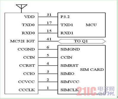
Figure 3 MC55 connection schematic
Fig.3 MC55Connection diagram
System software design
3.1 main program function
The main program is responsible for initialization, opening interrupts, analyzing and parsing GPS data, data transmission, and guiding the system into various corresponding working states. The main program flow chart is shown in Figure 4a.
3.1 GPS data receiving program design
The vehicle terminal device needs to extract valid information from the GPS positioning information, so it is also necessary to understand the meaning of various NMEA data. Only the GPS Minimum Data Output Statement (GPRMC) output examples are listed below. Output examples: $GPRMC, <1>, <2>, <3>, <4>, <5>, <6>, <7>, <8>, <9>, , *70. <1>: Greenwich time; <2>: information status, 'A' information valid 'V' information is invalid; <3>: latitude; <4>: northern hemisphere or southern hemisphere mark, northern hemisphere (N) or southern hemisphere (S); <5>: Longitude; <6>: Eastern Hemisphere or Western Hemisphere Mark, East (E) Hemisphere or West (W) Hemisphere; <7>: Ground Speed; <8>: Ground Direction; <9>: Date.
When the GPS module has data output, the MCU enters the serial port interrupt program. The program first determines whether the data header flag is "$GPRMC". If it is judged that the data is correct, the program enters the data receiving mode until the reception of "*" indicates that the data reception is successful, otherwise the exit interrupt program waits for the arrival of the next data. The following is a partial interrupt program code.
While ((IFG1 & URXIFG0) == 1);
{ UART0_RX_BUF[num++]=RXBUF0;
If (UART0_RX_BUF[0]!='$') num=0;
If(num==5)
{ if (UART0_RX_BUF[2]!='P') ​​num=0;
If (UART0_RX_BUF[3]!='R') num=0;
If (UART0_RX_BUF[4]!='M') num=0;
}
If (num==56)
{ for (i=56;i<73;i++)
{ if (UART0_RX_BUF[i]!='*') num=0;
Else k=i; }
}
}
}
3.3 GPRS data transmission program design
The taxi GPS positioning system can send the real-time information of the vehicle to the taxi monitoring and dispatching center through the GPRS module to monitor the dispatching center to master the running status of the taxi. After receiving the GPS data and parsing the valid information, the MCU stores the information (latitude, longitude, speed, etc.) that needs to be sent to the monitoring and dispatching center to the data transmission buffer for calling when the data is transmitted. This design uses the timer interrupt mode for data transmission. The transmission interval is 5S. When the timer expires 5S, the data transmission program is executed, the data in the transmission buffer is called, and the data is sent to the taxi monitoring and dispatching through the GPRS module. center. The data transmission program flow chart is shown in Figure 4b:
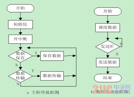
Figure 4 program flow chart
Fig.4 Program Flow Diagram
in conclusion
At present, the vehicle GPS positioning system has been applied to various industries of civil and military use. In the design of the taxi GPS positioning system in this paper, its hardware and software are modular design, easy to upgrade and maintain. After the actual vehicle test, the rental GPS positioning system has stable performance, the accuracy of data collection and the correct rate of sending data have reached the pre-design requirements. It provides a good operation platform for taxi company monitoring and dispatching. The system has good promotion value and application prospects.
The FirstPower CFPS(2V) and LFPS(6V/12V) series stationary batteries (Opzs Battery) are the newly products which were developed at the end of 2005.
The performances meet the standard DIN40736 and IEC60896-21...Characteristics Positive plate: It is a tubular plate that can prevent the active material from falling off. The grid of positive plate is Pb-Sb multi-alloy
Separator: With the combined application of porous rubber and porous PVC, the separator has a high porosity and good corrosion-resistance
Acid-proof bolt: It is of a special shape of funnel having the function of filtering acid smog and retarding flame. It can measure the density and temperature of electrolyte.
The design life is more than 20 years
Ensuring sufficient electrolyte for battery discharge
Storage Power Opzs Battery,Solar Storage Battery Opzs Battery,Opzs Battery
Firstpower Tech. Co., Ltd. , https://www.firstpowersales.com