Application of oscilloscope in maintenance diagnosis
This article refers to the address: http://
As a maintenance person, how to quickly and accurately capture anomalies and find the cause when diagnosing a vehicle failure is the key to solving the problem, and the oscilloscope is an important helper to help maintenance personnel solve this problem (Figure 1). This is a brief analysis of the application of the oscilloscope in maintenance diagnostics.
1. The role of digital oscilloscope in vehicle maintenance
Some signal changes in automotive electronics are very fast, and the cycle of change is one thousandth of a second. Usually, the scanning speed of the test instrument should be 5 to 10 times that of the signal under test. Many fault signals are intermittent, sometimes not, which requires the instrument to test faster than the fault signal. Digital oscilloscopes can meet this speed requirement. They can not only capture circuit signals quickly, but also display them at a slower speed so that maintenance personnel can observe and analyze them. It can also record the signal waveform in a stored way, and can back up to observe the fast signal that has already occurred, which provides great convenience for analyzing the fault. Whether it's a high-speed signal (such as a fuel injector signal) or a low-speed signal (such as a throttle position change and an oxygen sensor signal), an oscilloscope can be used to observe the waveform. The oscilloscope is like a ruler. It can measure the working condition of a computer system. The oscilloscope can observe how the automotive electronic system works.
2. Application of oscilloscope in the case of automobile failure
When the car's electronic equipment or wiring fails, the maintenance personnel need to start collecting all relevant data. An oscilloscope can display the trajectory of electron motion in a circuit by displaying the voltage over time as a curve. The magnitude of the voltage shown depends on the current and resistance in the circuit. Depending on how the voltage on the oscilloscope changes over time, you can determine what is wrong with the circuit. To get the most out of your oscilloscope, you need to compare the acquired waveforms.
Here are a few examples of how the oscilloscope helps us find the cause of the failure.
1Dongfeng Honda Civic diagnosis of intermittent flameout
A 2006 Honda Civic 1.8VTi sedan, the phenomenon of failure is intermittent flameout. Connect the oscilloscope to several lines of the engine control unit. In Figure 2, the red line (channel 2) is the camshaft position sensor signal, the green line (channel 3) is the crankshaft position sensor signal, the blue line (channel 4), the white line (channel 5), the purple line (channel 6), and the orange The yellow line (channel 7) is the control signal for the four injectors. This set of waveforms is recorded by the oscilloscope when the engine is about to turn off. Please note that the fuel injection sequence of the injector is now disordered, and the purple and orange lines indicate that the injector control signal is simultaneously injected. In addition, the injector represented by the orange line has been turned on twice in the same period of time compared to other injectors. It is important to note that the camshaft position signal represented by the red line and the crankshaft position signal represented by the green line are not problematic at this time. Now that we have this information, let's analyze it to find clues for the next step of troubleshooting.
The two main timing signals of the engine control unit are the input signals of the camshaft position and the crankshaft position. These two signals are normal and there is no fault, so it can be determined that these two signals cause the fuel injection to malfunction abnormally. Once the injector injection sequence is disordered and the number of starts increases, the engine control unit is in a cleared state. The clearing of the control unit is caused by a disorder of the internal clock or timing signal. The internal clock or timing signal is used by the program to time and issue a work order within a determined time. When the timing signal of the timing signal or the logic circuit has a problem, the program for controlling the main functional components of the engine will be in error, and as a result, a running fault will occur. The engine control unit enters the clear state for several reasons: internal clock error, input timing signal error, power or ground circuit failure, and interference signals entering the engine control unit.
In order to find out the cause of the zeroing, the oscilloscope is required to simultaneously monitor the fuel injection and ignition signals.
In Figure 3, the yellow, red, green, and blue wavy lines are the control signals for the injector, and the white, purple, orange, and brown wavy lines are the independent ignition coil (COP) control ignition signals. In this set of waveforms, the injector's signal is synchronized with the engine's ignition signal, which is key. From this set of waveforms, you can see the cause of the fault. Please pay attention to the yellow line and have a negative spike signal on the right side.
In order to properly analyze this spike signal, the oscilloscope should be set to dual channel display mode so that the waveforms can be superimposed to make it easier to see the relationship between the waveform signals (Figure 4). Now, it can be clearly seen that the white line (channel 5) is aligned with the spike signal on the yellow line (channel 1), and the falling edge of the white square wave signal is the signal that controls the ignition of the coil.
The cause of the vehicle's failure is the presence of carbon marks between the primary and secondary windings of the ignition coil. When the resistance between the spark plug electrodes is greater than the resistance of the carbon traces, the current will take a shortcut, that is, from the carbon traces of the primary winding. Since the primary winding of the ignition coil is connected to the power supply circuit and the control circuit, the induced high voltage generated in the secondary winding can find a loop from the integrated circuit of the engine control unit. The high voltage input to the engine control unit affects the operation of the internal clock in the processor. As a result, the fuel injection sequence and injection time of the injector are disturbed, resulting in a running failure.
Please note that a negative spike signal is only present in the control circuit of an injector. This is a common problem when there is a carbon mark between the primary winding and the secondary winding of the ignition coil. This negative spike signal is usually present in the waveform signal of the injector. The ignition coil is a negative discharge because the winding method is such that the center electrode of the spark plug is the negative electrode and the side electrode is the positive electrode. The reason is that the insulated center electrode can maintain a high operating temperature, and the high temperature tends to cause electrons to ignite in the breakdown gap between the spark plug electrodes.
When looking at clutter or spikes in a waveform, it is usually necessary to superimpose the measured waveform signals or display the signals in a strip chart (or a graph) so that they can be compared with other waveform signals in real time. The cause of the failure. The oscilloscope does not display a spike signal in the trigger mode. The spike signal in Figure 3 appears after the injection pulse signal ends. Negative spikes in the waveform signal are mostly caused by problems with the ignition coil. The car was faulty because there was an ignition coil abnormality, and the fault was eliminated after changing the ignition coil.
2 Buick Regal fault diagnosis during driving
A 2006 Buick Regal 2.5L sedan, the fault is an intermittent flameout failure. The engine of this car will be turned off when the vehicle is running, and then the car can be driven. The data of the engine control unit in Figure 5 is collected when the engine is about to turn off. The yellow line is the IC control signal (the signal required to provide fuel control and calculate the ignition advance angle to the engine between the ignition module and the engine control unit under normal operating conditions), and the red line is the bypass control signal (in the start or IC circuit) In the event of an anomaly, the engine control unit is provided with fuel control and the signals required to calculate the ignition advance angle. The green, blue, white, purple, orange, and brown wavy lines are all injector control signals. This set of waveforms shows that the injector was working properly at first, then there was a problem and the fuel injection pulse width increased. This indicates that the engine control unit has entered the clear mode. What is the cause of the engine control unit entering the clear state? this point is very important.
By setting this set of waveforms to the superimposed mode, you can see the relationship between them (Figure 6). Amplify the waveform before the fault occurs. Please note that the bypass control signal (red line) is the first problem, then the IC control signal (yellow line) is faulty. In combination with the operating principle of the ignition system of the vehicle, this sequence indicates that the fault is caused by an internal fault of the engine control unit or by a fault in the power supply circuit or the ground circuit.
If the IC control circuit fails before the bypass control circuit, it indicates that the sensor has a problem. To determine the cause of the engine control unit entering the clear state, connect the probe of the oscilloscope to the power supply circuit or ground circuit of the engine control unit and record the waveform at the time of the fault. If there are no interfering signals or spikes on the power and ground circuits, the cause of the fault is that the engine control unit is broken. If there are interference signals or spikes on the power and ground circuits, then the problematic circuit needs to be repaired. The car has no problem in the power supply and grounding circuit when the fault occurs. Changing the engine control unit and matching it solves the problem.
This article is just two examples of using an oscilloscope. The oscilloscope has many uses in maintenance. The oscilloscope can come in handy as long as there is voltage in the line. Once you've used an oscilloscope, it will give you a lot of things about electrical and electronics. An oscilloscope allows you to quickly understand the working state of an electronic circuit. More importantly, when the electronic circuit goes wrong, it can help you find the root cause of the problem.
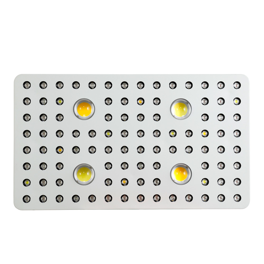
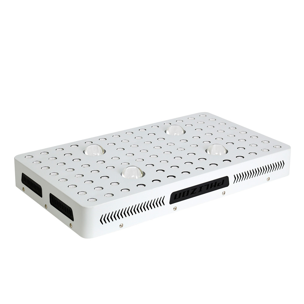
Phlizon`s COB series Grow Light emits all the wavelengths of light which can be fully absorbed by the plants to create.
Best full Specturm designed to perfectly match large areas of indooor plants, especially for Medical Plant.
COB + Dual-chip,most efficient spectrum,high PPFD.Two cooling fans with double ball(import from Japan) and big aluminum heat sink to protect the grow lights from high temperature,good cooling,long lifespan.Photosynthesis and promote healthy growth budding and flowering.
1000w/2000w /3000w cob led grow light, it will give you more options when your plants need different strength of illumination.
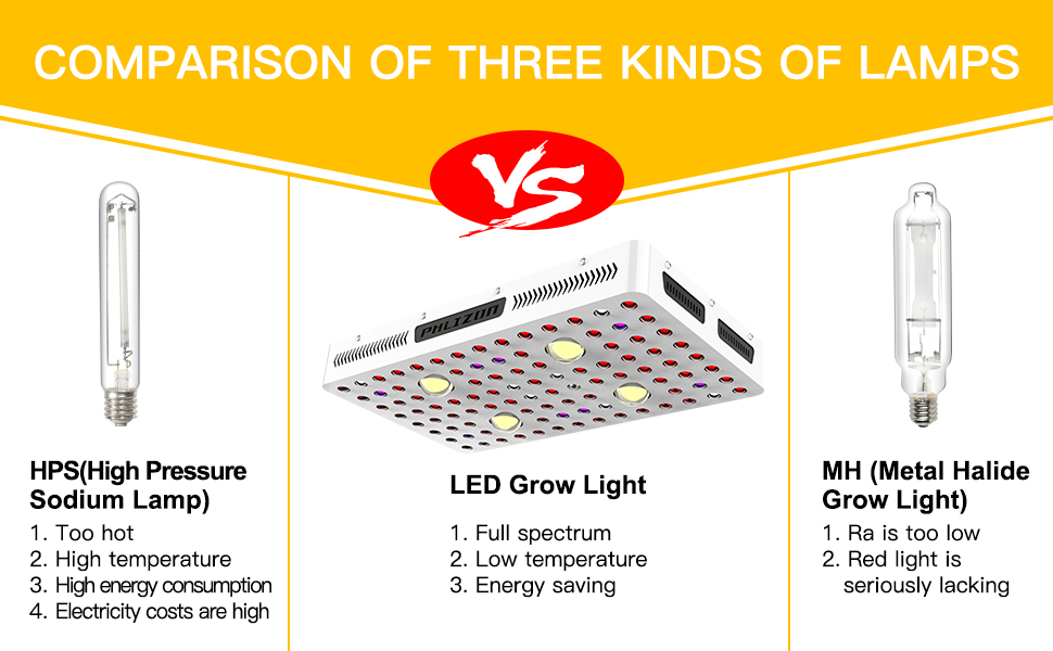
Grow Lights are a great choice for growers who are dealing with hot HPS lights and want to change to something that's going to run cooler. Although LED Grow Lights do produce heat,the smaller models might not bring up the temperature of your grow space.Even the more powerful models of Led Grow Lights that produce a lot of heat still have built-in cooling systems to help prevent the heat from beaming directly down onto your plants.
2000w COB LED Grow Light Features
Indoor grow light
COB series, high power branded CREE COB with high Par value and deeper penetration
VEG/BLOOM and STRONGER switches for each grow stage.
Special spectrum for plant growing to increase the yield.
Building to Harvest: Beneficial for seeding to fruiting stage.
Good quality fans with low noise.
Easy to install by minute
Energy Saving, environmental friendly
3 Years Warranty
Compare led grow light to traditional HPS/MH grow light

WHAT MAKE UP AN EXCELLENT Led Grow Light ?
1.PPFD Value : PPFD is Photosynthetic Photon Flux Density. When you choose a plant light, you should compare the PPFD values of different plant lights. The larger the value, the better the growth of the plant.
2.Actual Power: Because the actual power of the plant light always varies with different conditions, all Amazon sellers use the rated power to describe the power of the product because the rated power is constant. When you pick a LED grow light, the rated power of the plant light is a reference, and more importantly is the actual power.
3.Core Coverage: In addition to the above two, when you choose a plant light, you also need to compare the cover area of different plant lights, of course, the size of the core coverage area. In general, in germination stage, you can hang the plant light higher and the cover area is larger. In flowering stage you can hang the plant light lower and the cover area is smaller because the plant needs more light at this stage. You have to compare different coverage areas to choose the plant light that suits you.

Detailed images of 2000w cob led grow light


Applications
Hydroponics, Horticulture, Agriculture and Greenhouse
Locations: Farm, Exhibition, Garden, Home, Urban, Bonsai, and University Lab
Growth of Fruits, Vegetables, Flowers and so on
Seeding, Rooting, Breeding, Flowering and Fruiting period

Packaging and Shipping

2. By Air or by Sea for batch goods, for FCL; Airport/ Port receiving;
3. Customers specifying freight forwarders or negotiable shipping methods!
4. Delivery Time: stock avaiable sample will be delivered immediately ; 3-7 days for trial order; 7- 25 days for batch goods
Suggestions:
1.Clean the dust inside every 6 months to ensure the good heat dissipation and long life time.
2.Don`t keep too short distance to the plant canopy to avert leaves bleaching.
3. Highly hang the lamp will weaken the energy and affect the growth cycle of the plants, so the lamp should not be hang too high.
4. While taking care of the plants, please spray the leaves and branches 2-3 times everyday, to ensure the plants do not wrinkle a wither, and have no phenomenon of few fruit, and hard pericarp
Trade Terms
Payment: T/T, L/C, Paypal, 30% deposits before production, 70% balance to be paid before deliverying(Western Union are welcome)
Sample will be delivered within 7 working days.
Discounts are offered based on order quanlityes.
MOQ:sample order are acceptable
Delivery ways:DHL,UPS,FedEx,TNT, door to door,by sea,by air,etc.
If you are interested in, and
1.own several store for agriculture in your local market
2.or in the business of grow light equipment
3.or good relationship with grower or greenhouse owner
To be a distributor, max support will be offered:
1.price support
2.technical support
3.new product support
4.24 hours after-sales service online
PH-B-L4
cob led grow light,led grow light,led grow light cob,full spectrum led grow light,2000w led grow light
Shenzhen Phlizon Technology Co.,Ltd. , https://www.philizon.com
