
Introduction
A battery serves as a power source that releases electric energy during discharge and absorbs and stores energy during charging. In an underwater robotic system, a low-voltage power supply utilizing a lithium-ion power battery plays a crucial role. Neglecting proper maintenance and management of lithium-ion batteries can significantly impact their efficiency and lifespan, potentially causing irreversible damage to the battery and consequently affecting the overall performance of the underwater robot. In severe cases, this could lead to safety hazards for the robot. Monitoring the parameters of the lithium-ion battery pack in real-time allows us to understand the battery's operational status and characteristics, aiding in effective maintenance. Hence, developing an online monitoring system for lithium-ion batteries is essential.
To achieve the monitoring of lithium-ion battery parameters, a parameter acquisition module is designed to collect voltage, current, temperature, and other critical parameters from the lithium-ion power battery. These readings are then uploaded to a microcontroller unit (MCU) via an A/D conversion module for processing, storage, and display.
Overview of the Lithium-Ion Battery Pack Monitoring System
The system employs a distributed data acquisition approach combined with centralized data processing. Voltage, current, and temperature acquisition circuits are separately designed and subsequently sent to a single-chip microcomputer for unified processing. The system structure is illustrated in Figure 2-1 below.
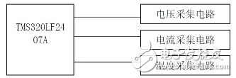
**Figure 2-1:** System Structure Diagram
This monitoring system is tailored for the lithium-ion power battery pack of a National 863 Project underwater robot, specifically the TS-LFP160AHA model produced by Shenzhen Leitian Technology. The battery pack comprises eight individual cells. Monitoring the terminal voltage of each cell is vital, requiring overvoltage and undervoltage judgments. Additionally, multiple temperature points need to be monitored—both the temperatures of each battery and the surrounding environmental conditions. Given the series configuration of the eight cells, only the total current needs to be measured, with overcurrent protection implemented.
This project utilizes the TMS320LF2407A chip. The benefits of using this chip in the battery monitoring system include:
1. **Energy Efficiency**: Modern electronic equipment increasingly emphasizes energy-saving designs. With secondary batteries powering the device, energy conservation becomes paramount. The DSP used in this design operates on a 3.3V supply, minimizing controller losses. Power management features include low-power modes that allow peripheral devices to operate at reduced power levels.
2. **Integrated A/D Converter**: The chip contains 16 A/D converter channels, which are beneficial for handling multiple acquisition sub-circuits. The output of the acquisition circuits can be directly connected to the DSP’s A/D conversion channels without the need for an additional external A/D conversion circuit.
3. **Flexible I/O Pins**: With 40 programmable or multiplexed I/O pins, the chip can effectively control safety switches and other peripheral circuits.
4. **Communication Interfaces**: The chip includes a Serial Communication Interface (SCI) and a 16-bit Serial Peripheral Interface (SPI) module, allowing integration with the monitoring system’s display component.
Hardware Design of the Monitoring System
The hardware design of the system primarily involves the design of voltage acquisition circuits, current acquisition circuits, and temperature acquisition circuits. The TMS320LF2407A chip is employed as the CPU. As a high-performance 16-bit fixed-point DSP device developed by Texas Instruments for real-time control applications, it features a command cycle of 33ns. Its integrated front-end sampling A/D converter and back-end PWM output hardware simplify hardware circuit design while meeting the real-time demands of the system.
Voltage Acquisition Circuit Design
This design manages a lithium-ion battery pack consisting of eight 3.6V lithium cells. Each cell has a nominal voltage of 3.6V and a fully charged voltage of 4.25V. The voltage acquisition accuracy is required to be within 1.5%, with a minimum sampling frequency of 20ms.
The system employs a linear optocoupler as the signal transfer and sampling device for the isolation and data acquisition system. This isolates the voltage of each cell at the front end, reducing the high battery voltage by a specific ratio to accurately reflect changes in the battery voltage to the DSP. The data is then fed into a multi-way switch for processing by the microprocessor. The advantage of optocoupler isolation lies in its fast speed (microsecond-level, far faster than the millisecond level of relays) and superior real-time performance. Furthermore, the signals at both ends of the optocoupler are entirely isolated electrically, ensuring no interference even in the event of an output short circuit. The optocoupler converts the voltage signal into a current signal, solving common issues associated with direct voltage sensing. Optocouplers are also more cost-effective compared to voltage sensors.
When selecting components, both economic feasibility and practicality were considered. The photodetector chosen was the TLP521 from Toshiba Corporation, and the dual operational amplifier TL082 was selected for operational amplification.
The voltage measurement circuit for the battery cell is shown in Figure 3-1.
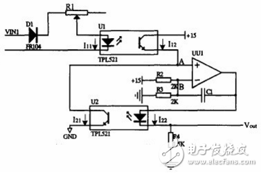
**Figure 3-1:** Single Cell Voltage Acquisition Circuit
Current Acquisition Circuit Design
Since all the cells in the lithium-ion battery pack are connected in series, only one current collection point is feasible.
In this design, a Hall current sensor is used for current acquisition.
The schematic diagram of the Hall current sensor is shown in Figure 3-2. The measured current \(I_n\) generates a magnetic field through the conductor, which is balanced by the magnetic field produced by the compensation current \(I_m\), regulated by the Hall element’s output signal flowing through the secondary coil. When the magnetic fields on the primary and secondary sides are balanced, the compensation current \(I_m\) accurately reflects the primary current \(I_n\).
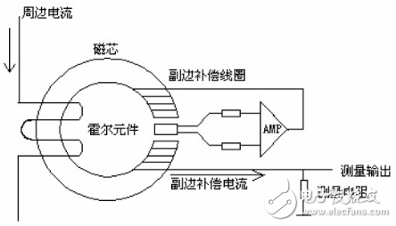
**Figure 3-2:** Hall Current Sensor Schematic
The system uses the closed-loop Hall current sensor of the Yusen CBH100SF model. The measurement frequency ranges from 0 to 100kHz, with a rated current of 100A, a measuring range of 0 to ±150A, a turn ratio of 1:1000, a precision of 0.2% to 1%, and a response time of 1μs. The structure is shown in Figure 3-3:
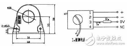
**Figure 3-3:** CHB100 Appearance and Connection Diagram
The sampling resistor \(R_m\) is sampled using precision resistors. High-precision metal film resistors with low temperature drift (not exceeding 2ppm) are recommended. Precision wirewound resistors should be avoided in high-frequency sampling due to their significant parasitic inductance. The sampling resistor's secondary output current rating should be less than the supply voltage, with a difference greater than 4V. The power of the sampling resistor must be sufficient, with \(R_m = 30 \Omega\).
Temperature Acquisition Circuit Design
In the calculation of remaining battery power, the operating temperature of the battery is a crucial factor. Real-time temperature parameter collection is also essential in assessing battery safety and implementing heat management strategies. In this design, the temperature signals of eight individual cells are acquired, along with real-time environmental temperature monitoring.
This system uses a thermistor to measure the temperature of the battery itself. Combined with a bridge circuit, the temperature signal is converted into a voltage signal. The circuit is shown in Figure 3-4.
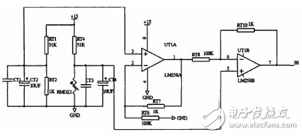
**Figure 3-4:** Single Cell Temperature Sampling Circuit
Here, \(R_{MDZ1}\) is a thermistor, chosen for its cost-effectiveness and compact size, making it suitable for direct attachment to the battery casing. Although the linearity isn't ideal, the main goal is to detect the upper and lower temperature limits, calculate the temperature differences between the batteries, and identify any anomalies. This doesn’t involve complex calculations or high functionality, so the use of thermistors suffices.
Environmental temperature is measured using the novel LM35 temperature sensor, which outputs a voltage proportional to the ambient Celsius temperature. Internally calibrated, it requires no external calibration. The sensitivity is 10.0mV/°C, with an accuracy of up to 0.5°C, a working voltage range of 4V-30V, low electrode consumption, and a low output impedance. To prevent sub-zero temperatures from causing issues during sampling into the DSP, a subtractor circuit is designed to adjust the ambient temperature range to [-45°C, 75°C], with an output voltage range of [0, 4.5V].
Software Design of the Monitoring System
The software design of this system employs C language programming for the DSP (TMS320LF2407A) and implements modular design, enhancing program readability and portability. The focus of this design is on the lithium-ion power battery used by underwater robots, aiming for broad compatibility. That is, minimal changes to the hardware are needed for different batteries; simply modifying the software suffices, ideally with little to no changes. The software is prepared for immediate use.
For this system, the control software should meet the following requirements:
- Collect current, voltage, temperature, and other signals, identify the battery’s fault signals, process the data, and implement appropriate protective measures while displaying fault information.
Analog data acquisition includes battery cell voltage, current, battery cell temperature, and environmental temperature. Voltage acquisition requires controlling an analog multiplexer switch, enabling time-divisional entry of individual cell voltages into the DSP. Simultaneous collection of voltage and current is essential. Utilizing the TMS320F2407A/D module, four quantities—voltage, current, battery temperature, and environmental temperature—are collected simultaneously, with the cycle completing analog sampling of multiple batteries in the battery pack.
Summary
Based on the characteristics and testing requirements of lithium-ion battery packs, this paper designs a monitoring system based on the TMS320LF2407A. A distributed data acquisition and centralized data processing scheme is proposed, providing software and hardware solutions for voltage, current, and temperature acquisition in the battery monitoring system. A bottom-level acquisition module framework for up to eight cells is established.
On this foundation, battery information can be conveniently collected into the DSP for recording, battery state estimation, and judgment. Communication with the central controller via the CAN network forms a complete battery monitoring system.
The primary research content of this topic involves the design of the overall scheme of the battery monitoring system and the hardware circuit design. At its core is the combination of decentralized data collection and centralized data processing. Individual cell voltages, circuits, and temperatures are collected separately and sent to the DSP for centralized and comprehensive analysis and processing. The hardware design focuses on the design of several acquisition circuits and the application of DSP small systems in the monitoring system. The voltage acquisition circuit offers flexibility and a clear price advantage while improving inter-channel interference and acquisition speed. It meets the real-time and measurement accuracy requirements of the system. By adding peripheral sample-and-hold circuits, simultaneous voltage and current collection is achieved. The current and temperature of the battery management system are measured using a Hall high-current sensor, thermistor, and Hall temperature sensor.
Servo Press Machine,Electric Cylinder Actuators,Servo Telescopic Linear Actuator,Electric Linear Actuator Cylinder
Suzhou Johnson Automation Technology Co., Ltd. , https://www.cn-johnson.com