
Abstract: According to the characteristics of weak acoustic emission signals, fast propagation speed, and susceptibility to interference, through the research on the types and methods of acoustic emission signal source positioning in acoustic emission detection, a design method for simultaneous acquisition of acoustic emission signals from multiple data acquisition channels . This method uses a single-chip technology to design a multi-channel acoustic emission signal acquisition system, thereby achieving synchronous acquisition of acoustic emission signals and sound source signal technology, and at the same time completes data storage and processing by communicating with the host computer.
Keywords: sound source localization; non-destructive testing; charge amplifier; weak signal detection; synchronous sampling; SPI communication
0 Introduction Acoustic emission technology, as a new type of dynamic monitoring technology, occupies an important position in nondestructive testing technology. Non-destructive testing technology is a more common and effective method in fault diagnosis. Therefore, the acoustic emission technology has broad application prospects in the online detection of fault diagnosis. Especially for large pressure vessels that are performing production tasks. Due to the long-term continuous work without stopping production, it is easy to cause fatigue damage to the pressure vessel and pose a serious threat to safety production. Acoustic emission testing can dynamically monitor large pressure vessels or storage tanks without interrupting production, and can quickly capture the location of defects, thereby effectively avoiding major accidents.
1 Acoustic emission signal characteristics and acquisition principles Acoustic emission (AcousTIc Emission) technology is a non-destructive testing and diagnostic technology that can be used to evaluate the damage of materials or components. Acoustic emission refers to a phenomenon in which a material generates a transient elastic wave by quickly releasing energy under the action of an external or internal force. The elastic wave released by the material reflects some physical characteristics during the destruction of the material, and the piezoelectric wave probe coupled to the surface of the material can convert the elastic wave generated by the acoustic emission source in the material into an electrical signal, and then apply electronic equipment Amplify and sample these electrical signals, and then transfer the collected data to the host computer for storage and analysis.
The elastic wave generated by the acoustic emission signal generated inside the material will be subjected to a combination of reflection, diffraction, and mode conversion during the propagation process, which will cause the attenuation of the elastic wave energy. The position of the sound emission source decreases with increasing distance. Therefore, when the deformation or crack formation point of the material propagates to the receiving point of the sensor, the detected acoustic emission signal becomes very weak.
The most important thing in the acoustic emission detection technology is to locate the acoustic emission source, and the method and method of the acoustic emission source positioning are determined by the number of channels of the acoustic emission signal acquisition system. One-dimensional line positioning requires two acoustic emission signal channels, while two-dimensional plane positioning requires at least three acoustic emission signal channels. Therefore, the four-channel acoustic emission signal acquisition is the most widely used acoustic emission signal acquisition system. On this basis, it can be expanded to more channel acoustic emission signal acquisition systems.
2 Acoustic emission signal acquisition system circuit design
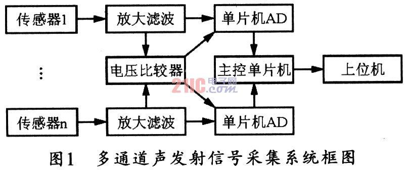
2.1 Composition of Acoustic Emission Signal Acquisition System Acoustic emission data acquisition system is mainly composed of sensors, preamplifiers, data acquisition, data communication, signal processing and other modules. Multi-channel acoustic emission signal acquisition system usually consists of four independent signal acquisition channels. This article will discuss the design of four independent signal acquisition systems in detail. Figure 1 shows a block diagram of a multi-channel acoustic emission signal acquisition system.
2.2 Amplifying and filtering circuit of acoustic emission signal Because the acoustic emission signal is very weak, it is necessary to choose an amplifier with high input impedance; and the charge amplifier has high input impedance and good linearity. Furthermore, because the acoustic emission probe is piezoelectric ceramic and has capacitive characteristics, choosing an ordinary amplifier will cause the static charge during operation to be poured back on the sensor plate, so that the sensor cannot output the detected signal normally. Therefore, in this system, the first-stage amplifier circuit selects the charge amplifier LF356. Figure 2 shows the charge amplifier circuit of the system.
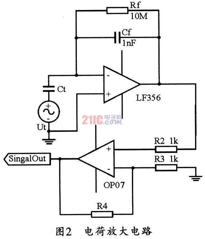
In the charge amplifier circuit, the resistance value of the resistor and the capacitance value of the capacitor must meet the signal frequency requirements of the sensor output: 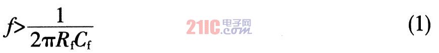
This design uses two stages of amplification. The amplification factor A of the first stage charge amplifier is designed to be 20, which is: ![]()
Among them: Ct is the equivalent capacitance of the transducer, the capacitance of the feedback capacitor Cf is 1 nF, and the equivalent capacitance of the transducer is 20 nF. In this way, Cf is 1 nF and Rf is 10 MΩ, then, bring the resistance and capacitance into the relationship can be obtained: 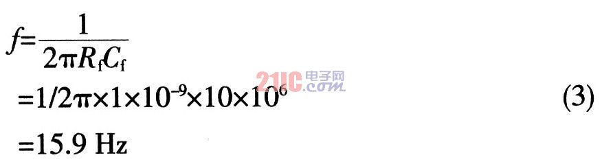
The frequency of the transducer output signal is greater than 60 Hz, that is: f> fx, which is greater than the cut-off frequency of the charge amplifier, which can meet the design requirements.
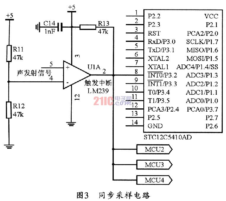
2.3 Synchronous sampling circuit In acoustic emission detection, one of the basic conditions for judging whether an acoustic emission signal is generated is the threshold voltage of the acoustic emission signal. When the signal is higher than the threshold voltage of the acoustic emission signal, an acoustic emission event is considered produce. In this system, a voltage comparator is set to detect the strong acoustic emission signal, and the reference voltage of the voltage comparator is the threshold voltage in the acoustic emission detection. The four independent acoustic emission signals in the system can enter the voltage comparator LM239 after being amplified and filtered. LM239 has four independent voltage comparator modules. When the signal enters the respective voltage comparison module, it can be compared with the threshold voltage. When the signal is higher than the threshold voltage, it is determined that the acoustic emission signal is coming, and the output of the voltage comparator is high at this time.
Due to the fast propagation speed of sound waves in the steel plate (the typical propagation speed is 3000 m / s), if the command time of multiple channels controlled by a central processing unit is not fast enough, it will cause asynchronous data collection. This article adopts the design scheme of “priority arrival and simultaneous triggering of four AD synchronization acquisitionsâ€.
Among the four sensors, the channel that preferentially receives the acoustic emission signal is also the channel that preferentially makes the output of the voltage comparator of this channel high, so the high level signal of this channel can be sent to the outside of the four microcontrollers Interrupt, and then start the on-chip AD of the four microcontrollers to collect the acoustic emission signals of the four channels at the same time. This fundamentally avoids the delay in the program due to the execution time of the instruction and other internal factors, such as asynchronous, multi-channel data acquisition caused by the acquisition of missing or incomplete acquisition and other problems. Its synchronous sampling circuit is shown in Figure 3.
2. 4 data communication The signal acquisition communication part of this system is divided into the lower computer, the data exchange system composed of SPI multi-microcomputer and the main control microcontroller and the upper computer communication two parts.
STCl2C5410AD MCU comes with SPI communication interface and built-in 8-bit shift register, which can ensure the accuracy of data transmission, and can simplify the circuit design and improve the reliability of the design.
The four microcontrollers in the four signal channels set in this design are all slave microcontrollers. They are controlled by the master microcontroller, and the slave microcontrollers that need to communicate can be selected through the slave selection line. The four slave MCUs can share the master input / slave output data line MISO, the master output / slave input data line MOSI, and the clock SPICLK bus. At the same time, they can save the collected data in the register of each slave microcontroller, so that the master can use the SPI bus to take out the data from each slave microcontroller, so that a data exchange system is formed by the SPI bus.
The communication with the host computer can adopt the serial port communication method, and connect the computer and the single chip computer through the serial port communication design, and then transfer the collected data to the computer in the order of the channel.
Finally, the host computer sends the password, and then the main control single-chip microcomputer transfers the collected data to the computer in the order of the channel.
3 Experiment and simulation The signal of acoustic emission can be simulated by the signal that the pencil lead with hardness HB breaks. The diameter of the pencil is 0.5 mm west, the lead length of the pencil is about 2.5 mm, and the angle with the surface of the steel plate is about 30 °.
The acoustic emission signal comes from the defect itself. Defects of the same size and nature will have different acoustic emission signals due to different positions and stress states. In the experiment, with the fixed sensor position unchanged, the pencil core was broken multiple times at the same point, and the state of the signal was observed. Finally, the situation where the acoustic emission analog signal appeared more frequently was selected as the state of the acoustic emission analog signal. Using STC12C5410AD single-chip microcomputer, it is an AD with 8 lO bits 100 ksps, fully meets the sampling theorem, and the chip has its own SPI bus, so the multi-channel acoustic emission signal acquisition system can be tested.
The test uses piezoelectric ceramics as the acoustic emission signal sensor, so it has the characteristics of simple structure, light weight and high sensitivity. Piezoelectric ceramics are sensitive to external forces and can convert extremely weak mechanical vibrations into electrical signals.
In view of the characteristics of the acoustic emission signal, the substrate material selected in this experiment is brass, the resonance frequency is 20 kHz, and the piezoelectric ceramic sheet with a capacitance of 20 nF is used as a transducer for the acoustic emission analog signal, which can meet the breaking signal of the pencil core. Receive the request.
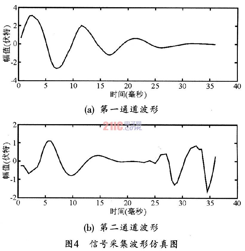
In this experiment, two channels of data acquisition were selected, two sensors were distributed on a steel plate with a thickness of 10 mm, and then the pencil lead was broken, and channel one and channel two were selected on the host computer, and then the two channels were collected. The data were uploaded to the host computer separately, and MATLAB was used to represent the collected data as a waveform. In this way, it can be seen that the amplitude of the acoustic emission analog signal is attenuated with time, which proves the energy attenuation of the elastic wave during the propagation process. At the same time, the interference phenomenon of the elastic wave also appears at the position of the sensor 2, which is caused by the longitudinal wave and the transverse wave of the elastic wave reaching the transducer 2 successively. Figure 4 shows the waveform simulation diagram of signal acquisition.
4 Conclusion According to the characteristics of acoustic emission, this paper proposes a design method of a multi-channel data signal acquisition system using the acoustic source localization method. Through a large number of experiments, it is proved that this design has the characteristics of fast data transmission and accurate positioning, which can meet the requirements of sound source localization.
XLPE Insulated PVC sheath Alloy Cable is kind of cable, in which the rare earth high compressed aluminium alloy is used as conductor, and PVC is used as Jacket wound around. The insulation adopts XLPE material, featuring with fire & moisture resistance. The whole structure is designed and manufactured elaborately based on advanced international technology and equipment. It has completely independent intellectual property rights and removed the defects of aluminum cable systematically. It applies to both dry and moist places at the temperature of 90ºC and under. This cable presents excellent mechanical performance.
Standard: GA306 Jacket: PVC
Conductor: aluminum alloy Cores: single core or multicores
Insulation: XLPE Feature: flame retarded
Rated voltage: 0.6/1KV, 8.7/10KV, 8.7/15KV, 26/35KV

Advantages:
- Conductor fatigue resistance
- Light weight
- Easy installation
- Long life span
- Flame retarded
- Decent mechanical strength
- Chemical & acid resistance
- Creep resistance
- Impact resistance
- Easy to bend
- Fire resistant
- Zero halogen & low smoke
- Corrosion & abrasion resistant
- ...

Application:
- For civil use
- For commercial use
- For industrial use
- Schools
- Large venus
- And many more...
Welcome to visit our factory to learn more about us. If you have any questions, please feel free to contact us.
XLPE Insulated PVC Sheathed Alloy Cable
XLPE Insulated PVC Sheathed Alloy Cable,XLPE Insulated Al Alloy Cables,Aluminum Alloy XLPE Cables,Al Alloy Armoured XLPE Cables
Smartell Technology Co.,Ltd , http://www.liencable.com