
1 Introduction
As the requirements of mobile operators increase, fiber optic repeaters are required to have monitoring functions. Therefore, the module adds FSK communication function on the original basis, which can facilitate the monitoring data transmission of the repeater system. This article describes the design and implementation of a FSK data communication system based on the RF transceiver chip CC1000.
2. Working principle of optical module
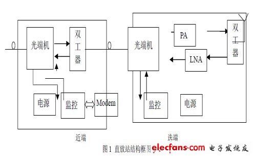
The uplink signal received by the antenna of the repeater is adjusted to a certain level by the amplifier and sent to the optical sending terminal. The radio frequency optical transmission module (hereinafter referred to as the optical module) carries the uplink signal together with the FSK-modulated monitoring signal. Light modulation and transmission through optical fiber. At the receiving end, the optical receiver converts the optical signal into a corresponding electrical signal and sends it to the base station. The monitoring signal is separated from the upstream signal by filter frequency selection, and then restored to a digital signal by FSK demodulation; similarly, the downstream signal from the base station is sent to the optical module for optical modulation and transmitted through the optical fiber. At the receiving end, the optical receiver converts the optical signal into a corresponding electrical signal, which is converted into the required power level signal by the repeater amplifier, and is transmitted by the antenna through the duplex circulator, thereby forming the optical fiber as Repeater system for transmission media. Its structure is shown in Figure 1.
3. FSK circuit design
3.1 FSK technology
FSK stands for "Frequency Shift Keying" and its English translation is "Frequency Shift Keying". The binary frequency shift keying is recorded as 2FSK.
It is an earlier communication method used in data communication. Because this modulation and demodulation method is easy to implement and has strong anti-noise and anti-attenuation performance, it has been widely used in low- and medium-speed data transmission communication systems. According to the recommendations of the International Telegraph and Telephone Advisory Committee (ITU-T), devices with transmission rates below 1200 baud generally use FSK to transmit data. Data is transmitted in fading channels (shortwave communication).
The working principle of FSK modulation signal generation is to transmit digital messages with the change of carrier frequency. In 2FSK, the carrier frequency changes with the modulation signals 1 and 0, where 1 corresponds to f 1 and 0 corresponds to f 2 ie:
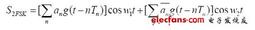
Among them: 1 w = 1 2Ï€ f, 2 w = 2 2Ï€ f.
There are only two numbers 0 and 1 in binary. One frequency is used when transmitting 1, and another frequency is used when transmitting 0. This is the essence of FSK.
3.2 Hardware circuit design
In this design, the wireless FSK transceiver chip is used, but the fiber transmission method is used because the fiber transmission is less affected by the outside world and the light loss during the transmission process is small, and the transmission distance is much greater than the wireless transmission distance. Because there are many types and numbers of wireless transceiver chips, the following factors should be considered when choosing a wireless transceiver chip: power consumption, transmission power, receiving sensitivity, the number of peripheral components required by the transceiver chip, and the cost of the chip. CC1000 is a programmable, half-duplex UHF single-chip transceiver chip manufactured based on ChipcON's SmartRF technology. It is mainly designed for 315, 433, 868, and 915MHz ISM and SRD equipment, and can be programmed to work at 300 ~ Any frequency between the 1000MHz range. At the same time, its sensitivity can reach -109dBm, programmable output power -20 ~ 10 dBm, FSK modulation data rate up to 76.8kBaud, can work in 2.7 ~ 3.3V low power supply, with 250Hz step frequency programmable frequency capability, suitable for jumping Frequency agreement. The main working parameters can be changed through serial bus interface programming, so it is very flexible to use.
In this design, the performance requirements for CC1000 in this system are as follows:
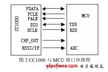
①Modulation rate: 9.6Kbps ② Encoding method: NRZ code ③ Transmission mode: asynchronous transmission UART mode ④ Frequency setting: transmission center frequency 433.916MHz, "1" 433.948MHz "0" 433.884MHz reception intrinsic frequency 433.766 MHz 32KHz⑥ Carrier frequency stability: ± 25ppm (ie ± 10KHz) ⑦ Receive sensitivity: ≤-90dBm The hardware interface circuit between MCU and CC1000 is shown in Figure 2. The MCU uses 3 output pins for the interface (PDATA, PCLK, PALE). PDATA must be a bidirectional pin to read back data, and another bidirectional pin is used for the data to be sent DIO and receive data, providing data timing DCLK should be connected to the input terminal of the microcontroller. In this article, CC1000 adopts asynchronous transmission UART mode. DIO is used for data input and TX connection of MCU serial port. DCLK is used for data output and connected to MCU serial port RX. The remaining pins can be used to monitor the LOCK signal at pin CHP_OUT, which is a logic high level when the PLL is locked. When an external termination resistor is used, the RSSI (Received Signal Strength Indication) voltage can be measured by A / D and the received signal strength can be detected. When designing a printed circuit board, it should be noted that it is required to use a double-sided PCB board, the ground plane is placed on the bottom layer to reduce the radiation and crosstalk of RF signals, and the ground pin should use a separate via, as close as possible to the package pin to ground, decoupling The capacitor should also be placed as close as possible to the power supply pin and connected to the ground layer through a separate via. The smaller the peripheral components, the better it is to use surface fixing devices.
4. Software design
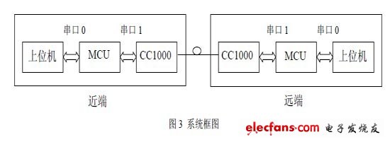
The transmission and reception of the overall system data is shown in block diagram 3. The MCU stores the data of the host computer through serial port 0, and after framing, it is transmitted to CC1000 from serial port 1 and out through the RF transmitter. The remote MCU performs corresponding processing according to the received data, and re-frames and transmits For the local PC.
Air Purifier Tube Lamp with Base,UV LED Germicidal Tube Lamp,Intelligent App Control Ceiling Lamp,Living Room Ceiling Light
Jilin Province Wanhe light Co.,Ltd , https://www.wanhelight.com