
Function of image software system
In the current image processing system for computer memory, the Windows operating system, PCI bus, single-screen operation mode are generally adopted, and image communication technology is also integrated. The current image software system should generally have the following functions:
1. Image input and output
The input of images mainly includes the image input of cameras, scanners, and digital cameras; the output of images mainly includes the image output of printers, video copiers, and monitors. To realize the function of embedding input and output devices into the image software system to complete image input and output, it is necessary to call or install device drivers of these devices.
2. Storage and loading of image files
The storage of the image file is to store the image in the frame storage or memory on the disk. The loading of the image file is to transfer the image file in the disk to the frame storage or memory. There is a problem with the image file format. The common BMP format is often used.
3. System management
The management of the system can be regarded as controlling the working state of the image hardware system. Such as the switching of input channels and output channels, the selection of storage, etc.
4. Image processing
There are many types of image processing, and the general categories are often used as the content of the first-level menu, such as grayscale conversion, image editing, image measurement, image enhancement, etc.
5. Image communication
Image communication includes the sending and receiving of images, and often involves the compression and transmission of images. Generally divided into static image compression and transmission and dynamic image compression and transmission. There are two image data sources for image compression and transmission: image data comes from the hard disk; image data comes from the hardware image system.
Hierarchical structure of image software system
Generally, the image software system is structured in layers. Figure 1 shows the layered structure of the image software system. The dotted frame in the figure is the image software system, where the bottom layer is the hardware driver layer, which mainly solves the connection problem with the hardware, the middle layer is the processing layer, and implements various algorithms. The top layer is data storage and communication.
In general, the following three methods can be used to drive hardware devices:
Provide high-level language calling subroutines;
· Provide installable device drivers;
· Provide universal device drivers.
In the Windows operating system, users can directly install drivers for devices such as printers and scanners. Because the Windows operating system already contains many peripheral device drivers, this is very convenient for users.
Image software system hardware device driver
The hardware device driver of the image software system should complete the following tasks:
· Operation of device configuration space on PCI bus;
· Operations on SAA7146 internal registers;
· Initialization of the video front-end subsystem;
· Maintenance of PC hardware interruption;
· Obtaining video image data buffer;
· Real-time display of video images;
· The realization of the overall software structure and special functions.
As can be seen from the data processing flow of the entire system, the image data buffer located in the host is the transfer link of the data flow from the external dedicated hardware platform to the host's internal general processing platform. The external image data is written into the buffer zone through the PCI bus interface control chip, and the internal software needs to read data from the buffer zone for processing and display.
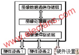
Figure Hierarchical structure of image software system
The magnetic buzzers (Self-drive Type) offer optimal
sound and performance for all types of audible alert and identification. Our
Magnetic Buzzer solutions are offered with various mounting options. We also
provide you with a washable version for your preferred soldering method. Our magnetic buzzers, also known
as indicators, are designed with an internal drive circuit for easy application
integration. During operation, current is driven through a voice coil to
produce a magnetic field. When a voltage is applied, the coil generates a
magnetic field and then allows the diaphragm to vibrate and produce sound. This
Buzzer type has a low operating voltage ranging from 1.5 – 12V+. Our magnetic
buzzers are desirable for applications requiring a lower sound pressure level
(SPL) and frequency.
Magnetic Buzzer Self-drive Type
Passive Buzzer,Dc Magnetic Buzzer,Electro Magnetic Buzzer,Magnetic Buzzer Self Drive Type
Jiangsu Huawha Electronices Co.,Ltd , https://www.hnbuzzer.com