An innovative design of an energy-saving and environment-friendly switching power supply
Switching power supply is the development direction of modern DC stabilized power supply. It is widely used in many fields of production, scientific research and teaching because of its small size, light weight and high efficiency. However, it is not easy to adjust greatly, and the output noise is high, which limits its application in high-frequency equipment, instrumentation and other fields. The output of the DC linear regulated power supply is greatly adjustable, and the output is noise-free, but there are defects of large size, heavy weight, and low efficiency. The new switching power supply is developed for the advantages and disadvantages of the two types of power supply, and thus obtained the utility model patent of the State Intellectual Property Office (patent number: ZL2007201531075).
This article refers to the address: http://
1 Brief introduction of the new switching power supply principle
As shown in FIG. 1, it is formed by sequentially connecting an anti-interference filter 1, a controllable rectification filter 2, a high frequency conversion switching element 3, a high frequency resonant converter 4, and a high frequency rectification and filtering output 5. Control of the conduction angle of the controllable rectification filter 2 is accomplished by the trigger signal control logic 8. The slow start circuit 7 causes the conduction angle of the trigger signal control logic 8 to be gradually increased from zero degrees when turned on. The output sampling and comparison amplifying circuit 10 compares and amplifies the output voltage of the high frequency rectified filtered output 5 with the reference voltage source, thereby controlling the trigger signal control logic 8 to stabilize the output voltage. By changing the size of the reference voltage source, the trigger conduction angle of the trigger signal control logic 8 can be changed to adjust the magnitude of the output voltage. The switching signal generating circuit 9 generates a square wave signal suitable for the high frequency resonant converter 4 for controlling the on and off of the high frequency switching element 3, so that the direct current electric energy enters the high frequency resonant converter 4, forming a high frequency current oscillation. And through the high-frequency transformer output to the high-frequency rectification and filtering output 5, reducing the switching noise. The auxiliary regulated power supply 6 supplies energy and reference power to the slow start circuit 7, the trigger signal control logic 8, the switch signal generating circuit 9, the output sampling and the comparison amplifying circuit 10.
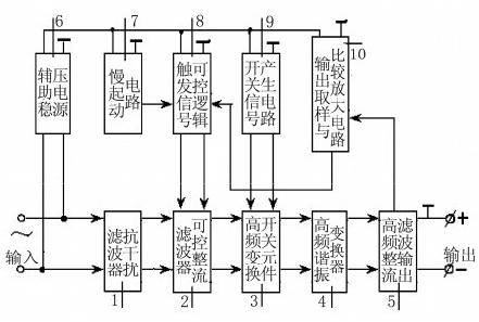
Figure 1 Schematic
2 Energy saving, environmental protection, high efficiency
Generally, the energy conversion efficiency of a DC linear stabilized power supply is about 30%, which not only wastes electrical energy, but also causes the whole machine to be prone to heat and the components to age quickly. Generally, the filter circuit of the switching power supply is a capacitor, and its AC impedance is small, which is easy to cause a surge current at the time of starting. To this end, a temperature sensitive resistor is added to prevent the surge current, thereby causing energy waste. Generally, the switching power supply adopts a square wave conversion form, and the square wave spectrum is rich, and it is difficult to filter by the filtering method. The noise level is about 2% of the output, causing interference to high frequency equipment and pollution to the industrial power grid. The new switching power supply is connected to the power grid through a controlled rectifier circuit. When the power is turned on, the conduction angle rises from zero. Without the temperature sensitive resistor, the excessive starting current is effectively controlled by the slow start circuit. The number of slow start circuit components is small and there is substantially no energy loss.
The method of physics resonant circuit is used to transform the square wave into an approximate sine wave, which overcomes the problems caused by square wave overshoot and undershoot, and reduces the noise level to less than 1‰ of the output.
3 output is stable and greatly adjustable
Generally, the switching power supply uses a method of adjusting the duty ratio to stabilize or change the output. But the duty cycle is limited. Therefore, the output of the general switching power supply is not fixed. The input of the new switching power supply uses a controlled rectifier filter whose conduction angle can start from zero.
When the output is unstable, changing the conduction angle makes it unchanged, which ensures the stability of the output. By controlling the conduction angle of the controllable rectification filter circuit---the method of controlling the input voltage of the switching power supply to stabilize and adjust the output, a new stable form of the switching power supply is created.
4 constant current and constant pressure, multi-purpose
One machine multi-purpose is one of the innovations of the new switching power supply. That is, the output can be converted from a constant current to a constant voltage. When the load changes continuously, the output voltage can be automatically changed to maintain constant current. This is not possible with normal power supplies. In general, when the output varies greatly, the power consumption of the adjustment tube causes problems. The change in the output voltage of the new switching power supply is tracked by the conduction angle of the controlled rectifier filter, which automatically tracks from zero to the design rating, keeping the voltage drop across the regulator constant.
The new switching power supply has many advantages such as creativity, energy saving and environmental protection. It can be used as an advanced power supply equipment for industrial and mining enterprises, scientific research institutions and colleges and universities, and has achieved good results in experimental teaching.
Fiber Connector is an important component, using in the fiber optic network. It is also the key part used in Fiber Optic Patch Cord and fiber optic pigtail.Main types of Fiber Optic Connectors are SC Fiber Connector,LC Fiber Connector, FC Fiber Connector , ST Fiber Connector ,MPO connector,MTRJ connector etc.Both Single mode fiber optic connector and multimode fiber optic connector are offered to fulfil with customers` demand.According to the polished ceramic end-face, it divides PC, UPC and APC.Meanwhile Fiber Connectors are available with different colors and diameter,which can be fit for FTTH projects.Fiber optic connectors are widely used for Fiber to home(FTTH),Local Areal Networks(LAN),Passive Optical Networks(PON),CATV,Fiber communication system,fiber transmission equipment, cable television networks,telecommunications networks,Data processing networks and optical test equipment and other telecom fields.Foclink,a reliable supplier of fiber connector,is always beside u 7*24.
Fiber Connector
Fiber Optic Connectors,Fiber Connectors,SC Fiber Connector,Fiber Optic SC Connector
Foclink Co., Ltd , http://www.scfiberpigtail.com