
In an isolated power supply, the secondary winding of the isolation transformer is ultimately connected to the chassis ground. Therefore, there is a considerable primary to secondary parasitic capacitance.
Figure 1 shows a simplified schematic of one such situation.
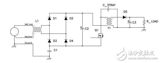
Figure 1 Q1 high voltage switch drives common mode current in C-STRAY
This is an isolated reverse structure that works offline. The 110 volt to 220 volt AC input supply is rectified to provide 100 volts to 400 dc to the power stage. The power switch quickly turns on and off, producing a 500 volt to 600 volt switching waveform on the Q1 drain, which is also applied to the primary winding of the power transformer. This switching voltage creates a current in the stray capacitance between the primary winding of the transformer and the secondary winding. This current flows through the preset chassis of the load or is only capacitively coupled to ground. This current must complete the noise return path to produce a switched mode power supply. In the absence of C1, it flows back to the AC input source and then into the input line of the power supply, which is likely to exceed EMI emissions specifications.
This current filtering is particularly difficult due to its high source impedance. The transformer has a stray capacitance level of 100 pF and a typical power switching frequency with an impedance of 10 kΩ. It is not practical to add an inductor to the current path to reduce this current. For example, if we want to reduce the current by a factor of 10, which requires a reactance of 100 kohms (ie 0.1 hen) and a distributed capacitance of less than 10 pF, this is not realistic.
Capacitor C1 brings another solution. It provides a local return path for the current. Most common mode current flows back through the capacitor inside the power supply instead of back through the AC input supply. In addition, C1 also reduces the power supply impedance of the system, so the common mode series inductance L1 becomes a reality.
A key factor in the design of the common mode filter is the choice of the C1 value. From electromagnetic interference (EMI)
From the perspective, the larger the value, the better. Larger capacitors allow for smaller EMI signals and lower source impedance. You can use the squared principle of capacitance to estimate the reduction in EMI signal. However, high capacitance also means that the line frequency of the rack connection is larger. In addition, this current has some safety restrictions to reduce the chance of electric shock. When the power supply frame is broken, an electric shock will occur when a person enters the current path, as shown in Figure 2. IEC Std 601-1 limits this current to 0.5 mA RMS, and more stringent safety regulations are being discussed. When the input is 230 volts, the IEC can effectively limit the C1 value to 4700 pF.
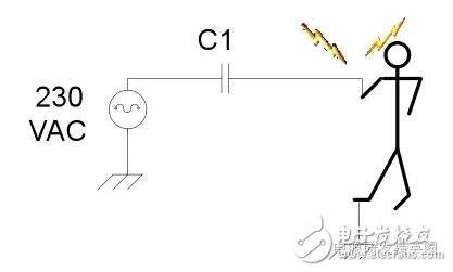
Figure 2 C1 can be a risk of electric shock
In summary, the high dV/dt voltage waveform that drives the parasitic capacitor chassis ground forms a common mode current. This current is particularly difficult to filter because of its high source impedance. Filtering requires the use of a rack capacitor to provide another local return path and reduce impedance. Although from the perspective of the EMI filter, the larger the capacitance, the better, but the total capacitance is limited by the safety regulations.
Vape Pen,500 Puff Cigarette,500 Puffs Disposable Vape,Electronic Cigarette Customizing
ALD GROUP LIMITED , https://www.aldvapor.com